
High-performance quadrature sine wave type oscillator circuit
The RC oscillator circuit described employs the HA5025 integrated circuit, which is notable for its four current feedback amplifiers. This design allows for the generation of four quadrature sine waves, which are essential in various applications, including signal processing and modulation schemes.
In this configuration, the phase shift unit is critical, as it determines the frequency stability and output waveform quality of the oscillator. The use of voltage feedback amplifiers allows for the amplification of the signal while maintaining a specific phase relationship, which is vital for oscillator operation. However, it is important to note that the gain of these amplifiers is frequency dependent. As the frequency increases, the gain diminishes, ultimately leading to a point where the amplifier cannot sustain oscillation if the frequency is not sufficiently high. This characteristic is attributed to the inherent phase shifts within the amplifier's feedback loop.
The quadrature outputs produced by the HA5025 can be utilized in various applications, including phase-locked loops (PLLs) and signal generation for communication systems. The four sine wave outputs are 90 degrees out of phase with one another, which is advantageous for applications that require precise timing and synchronization of signals.
In summary, the RC oscillator utilizing the HA5025 is an effective solution for generating stable and precise quadrature sine waves, with the design considerations of phase characteristics and frequency response being pivotal to its functionality.Many RC oscillators use the advanced circuits in the phase shift unit. They use the voltage feedback amplifier, and the gain of the voltage feedback amplifier will reduce sharply in the high frequency, and gain will stop, when it has not reached the high frequency. The difference of the voltage feedback amplifier phase characteristic is the reason. The high frequency IC HA5025, which contains four current feedback amplifiers, is used to make the RC oscillator, thus four quadrature sine waves will be formed, as shown in the picture. 🔗 External reference
Related Circuits
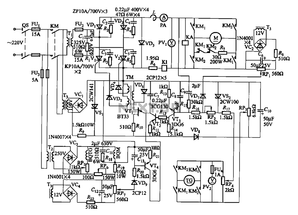
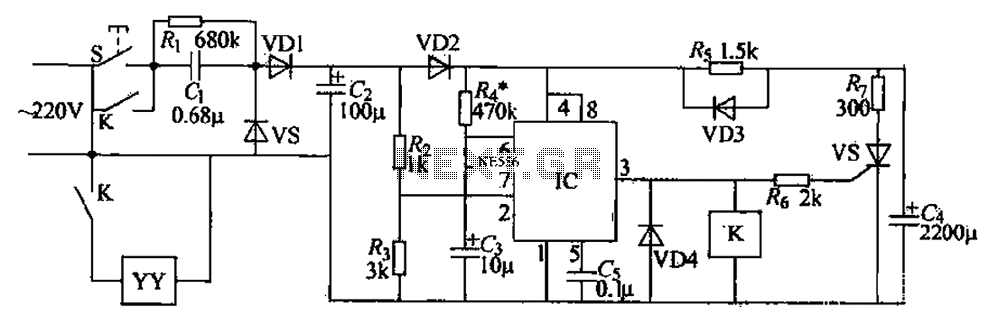
The circuit encompasses a main circuit, a trigger circuit, speed negative feedback, negative feedback differential voltage, a current cut-off circuit, loss of field protection, and other components. Given that the motor power is small (1.1 kW), a single-phase circuit...
This circuit utilizes a single 555 Timer IC along with a small transformer to generate high voltage for testing zener diodes with voltage ratings up to 50VDC. The 555 timer operates in astable mode, with the output from pin...
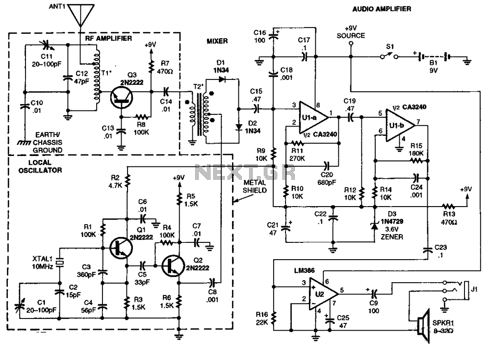
The RF amplifier Q3 connects to diodes D1 to D4 within the mixer. Transistors Q1 and Q2, through transformers T1 and T2, facilitate the injection of liquid oxygen at 10 MHz for diodes D1, operational amplifier U1A, and U1B....
The automatic toilet flusher is designed to restructure the traditional flushing mechanism, allowing for a single, reliable flush after each use. It features energy-saving capabilities and a long-lasting chip, ensuring ease of use even when disconnected from the power...
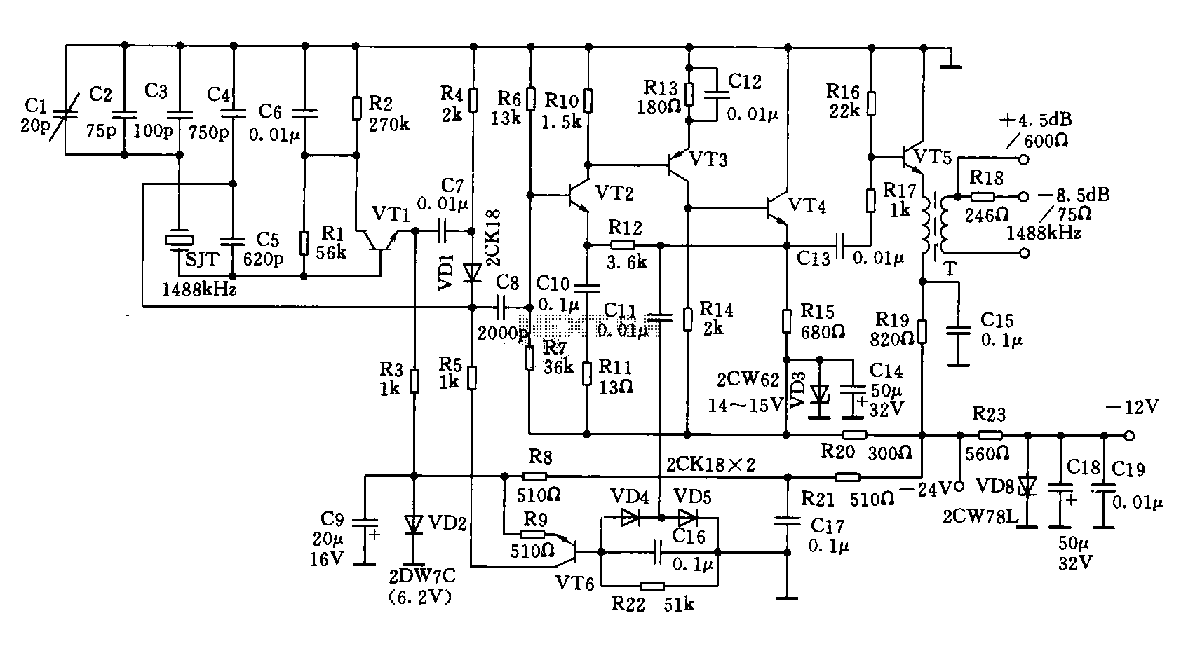
A 1488 kHz master oscillator quartz crystal resonator is utilized for frequency stabilization. The output from the frequency divider provides three different square wave signal outputs at 4 kHz, 12 kHz, and 124 kHz. The circuit includes transistors VT1,...
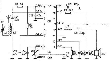
This AM radio receiver circuit utilizes the TDA1083 radio IC, which is suitable for constructing a simple medium frequency (MF) band radio. The schematic operates within a frequency range of 300 kHz to 3 MHz. The circuit is straightforward...