
applied robotics
The electrical design encompasses various components essential for the operation of the system. The Teensy 2.0 microcontroller serves as the central hub for processing input from the PC and managing communication with the Mega128. The MAX232 chip is critical for converting the voltage levels between the microcontrollers and ensuring reliable data transmission. The PWM control circuit for the solenoid incorporates a power MOSFET to handle the high current required for solenoid operation, along with a flyback diode to protect against voltage spikes when the solenoid is de-energized.
The motor control circuit, which utilizes a motor controller chip, is designed to direct the DC motor's operation based on the logic levels received from the Mega128. The integration of a rotary encoder allows for precise control of the trolley's position, enabling accurate lateral movement. The mechanical system's design, including the lead screw and solenoid, is optimized for efficiency and performance, ensuring that the robot can effectively manipulate the pucks on the playing field.
Overall, the project integrates a variety of electronic components and control systems to create a functional robotic platform capable of detecting and interacting with pucks on a board, demonstrating the effectiveness of combining mechanical and electrical engineering principles.Mostly everything has been put together for the electrical portion of the project. Serial communication is almost working and will be used in conjunction with a Teensy 2. 0 chip to communicate through serial USB and the mega128. A TTL UART serial driver such as the MAX232 needs to be purchased in order to communicate between teensy and mega 128. The PC will send data via USB to the Teensy, then the teensy will relay this information to the mega128. This was something that was discovered after making a DB9 to DB9 serial cable and realizing that no new computers have a DB9 serial port. We all ready have a Teensy 2. 0 on hand, and code just needs to be tested for the communication and the MAX232 circuit needs to be built.
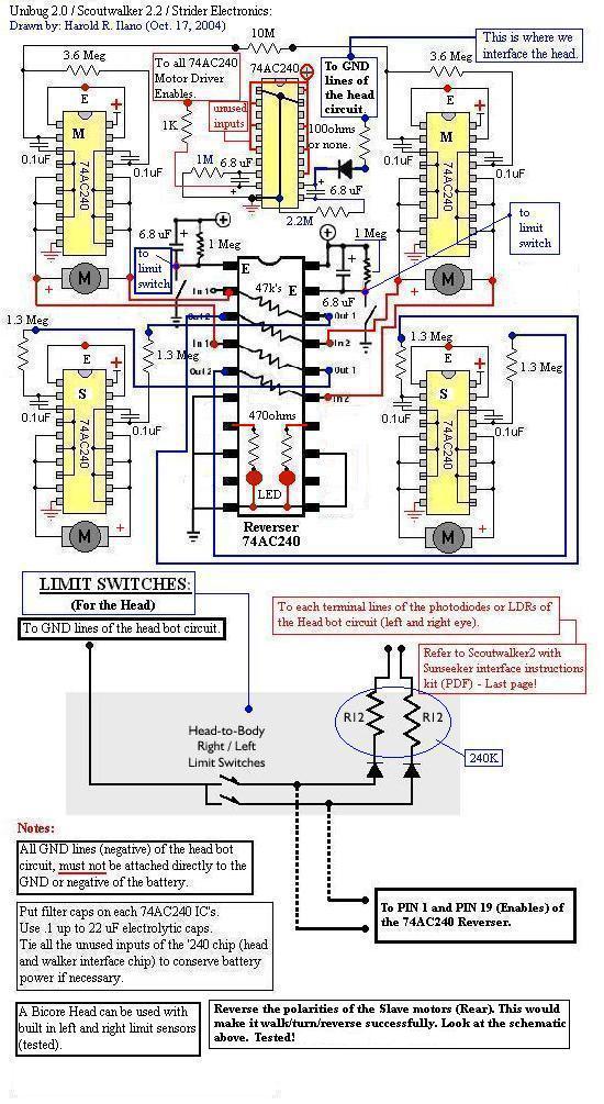
This design has already been proven, and example code for USB routines can be found HERE. Here is a schematic to be used with the teensy and MAX232: PWM for the solenoid has been successfully written and tested with our solenoid at full power. A circuit was created to pulse the voltage of the solenoid using a power mosfet, flyback diode, and power mosfet driving stage.
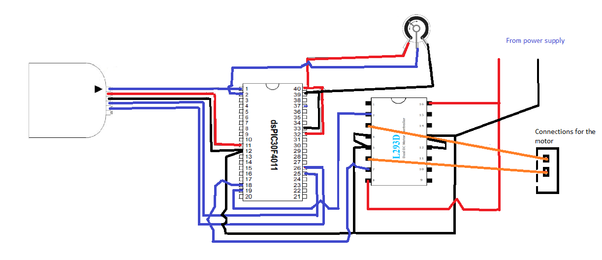
A circuit can be found below: Basically, You de-assert the disable pin, connect a DC motor to M1a and M1b, and based on whether Phase 1 is logic high or low, the motor will turn clockwise or counter clockwise. The motor controller chip is powered by 12V, and the hex inverter is powered by 5V. Logic levels from the mega128 are 5V high and gnd low. For the software we have usedMATLABto handle the computer vision. We have taken three different pictures that we can use in order to calibrate and proof our finding algorithm.
Below are four pictures whereMATLABhas found all the blue pucks. After finding all thepucksthe system finds the closest puck and outputs the position. The current system demonstrates that we can find pucks but does not provide much gamestrategy beyond smacking the competitors pucks away. Our design employs a single degree of freedom for positioning the puck, lateral movement. Out previous design used and additional D. O. F. (rotation), but it was decided to not offer enough of an advantage to justify the additional cost and time to build and control.
In the physical world, this is accomplished with a trolley which moves laterally via a lead screw. Our mechanical design utilizes a solenoid to provide the accelerating force for the puck. We chose a solenoid over a spring and latch system because the it is far easier to machine and assemble, more compact, lighter, and just as easy to control. The drawback to using a solenoid system is that they are harder to model and tend to be more temperamental than a spring and latch system.
The component that will actually interact with the puck will be a gripper with two "fingers. " The reason for this choice instead of a simple saddle is that it will prevent the puck from dislodging from the gripper while the trolley moves. The fingers will also make sure that the puck is properly seated which is very important due to the solenoid`s somewhat short stroke length of 1.
5". An advantage to the gripper is that it allows for a larger position tolerance for the loading of the puck. The robots only "sense" will be sight, which will be provided by a high camera (720p webcam). It is hoped that the high resolution will allow the robot to more accurately sense the position of pucks on the board.
The camera will be mounted above the rest of the robot on a mast in order to provide a better viewing angle of the board than a camera at a lower angle. Now to answer the question of "how do we plan to control all of this " The trolley will be moved using a drive screw which will be powered by a high speed DC motor in combination with a rotary encoder.
The solenoid will be controlled using a micro-controller and powered by two 12V car batteries in series. Small servos will open and close the fingers. Electrical: At first, I was trying to drive the powe 🔗 External reference
Related Circuits
BEAM enthusiasts often quickly learn to scavenge necessary components for their projects from technoscrap. However, there will always be occasions when purchasing new parts or materials becomes essential. This trend is increasingly prevalent as Application Specific Chips are being...

The FTDI DLP-USB245M is a USB-to FIFO interface module that simplifies the control of multiple stepper motors by a PC. The FTDI DLP-USB245M module is designed to facilitate communication between a PC and various electronic devices, specifically enabling the control...
This is an attempt to create a simple and compact photovore. Although it may not be visually appealing, it serves as a good starting point for beginners. It is a personal version of the Dozer photovore. The latest robot...
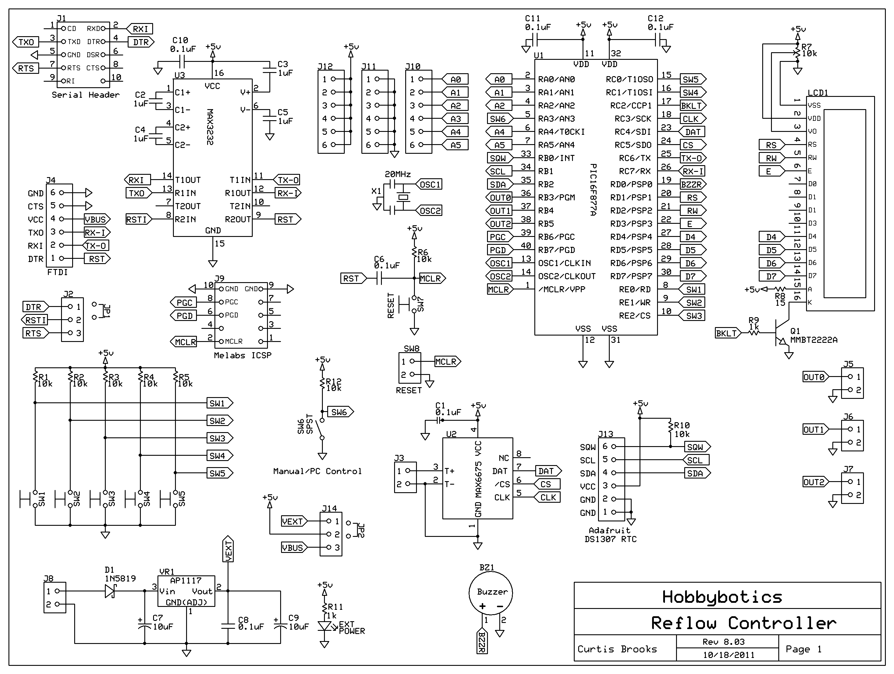
Introduction to the Reflow Process and PID Controller Circuit Documentation. This document discusses the benefits of using Surface Mount Devices (SMD) in circuit design, highlighting advantages such as reduced size and cost compared to traditional through-hole components. The reflow soldering...
For this experiment, a light-dependent resistor (LDR) was utilized to control the speed of a DC motor through a voltage divider configuration. The LDR was connected in series with a resistor, and the output was taken from the center...
RF technology is an exciting field to incorporate into electronic designs. However, for beginners, constructing reliable RF transmitters and receivers can be challenging. RF (Radio Frequency) technology plays a crucial role in modern communication systems, enabling wireless data transmission over...