
APRS GPS Controller
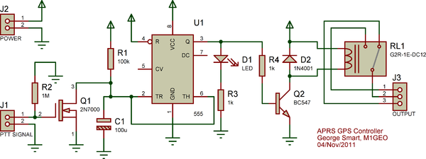
The circuit design integrates a NE 555 timer configured as a retriggerable monostable multivibrator. The timer is set up to maintain its unstable state until the PTT line voltage drops significantly, at which point the timer begins its timing cycle. The 2N7000 MOSFET plays a crucial role in controlling the capacitor's charging state; it effectively prevents the capacitor from charging when the radio is transmitting, ensuring that the timer does not inadvertently trigger the GPS shutdown.
The design includes a capacitor connected to the threshold pin of the NE 555 timer, which charges until it reaches a voltage level of two-thirds of the supply voltage. The timing period can be adjusted by changing the resistor and capacitor values in the circuit. When the PTT line is active, the MOSFET keeps the capacitor shorted, maintaining the timer in its unstable state. Once the PTT line goes low, the timer begins its countdown, and the capacitor starts to charge. If the PTT signal returns before the timer reaches its threshold, the MOSFET will reactivate, preventing the GPS from powering off. However, if the radio is powered off, the PTT line will not return, allowing the timer to complete its cycle and subsequently power down the GPS.
This design ensures that the GPS and Tracker remain operational during brief transmission interruptions, effectively utilizing the radio's power management capabilities while minimizing unnecessary power consumption. The overall circuit efficiency and functionality make it suitable for applications in APRS systems, where maintaining GPS operation during radio use is essential.the Yaesu FT-7900E (radio)`s power status to guide the power status of the GPS and Tracker would be ideal - this doesn`t require any additional cabling and, if done properly, would allow for the radio`s Auto-Power-Off to turn the GPS and Tracker off should I forget to do so myself! Excellent! There is of course one blatant issue; when the radio transmits the PTT voltage would be low, as to signal the radio had powered
off, and; the 9K6 line would also be silent while transmitting, as to indicate once again the radio was off. A simple monostable circuit, perhaps using a NE 555 timer would allow for these `silent` periods to be smoothed out for a short time, say 1 minute.
This way, the GPS & Tracker would stay on for 1 minute after the radio powered off; after a minute the GPS & Tracker would power down also. As you can see, keying the radio from the microphone does not effect the PTT line voltage enough to matter, and the signal is indeed changed when the radio is powered off.
The solution is what is called a retriggerable monostable. A monostable timer is a timer that has a fixed time element to it; it is unstable in only one state and after a specific time (hear this time is a parameter we can choose) it returns to it`s one stable state. With the NE 555 IC, this stable state is once the capacitor is charged to over 2/3rds of the supply voltage.
By using a 2N7000 MOSFET, we can short this capacitor preventing it from charging at all, therefore holding the 555 in it`s unstable state. When the PTT line drops, the MOSFET stops shorting the capacitor, and the 555 starts timing as usual.
If the radio was transmitting an APRS frame, then after a few seconds, the PTT voltage will reappear, the MOSFET reconduct and short out the capacitor once more - the net effect is that the capacitor never got to 2/3rds of the supply voltage and so the GPS was never turned off. If on the other hand the PTT voltage disappears due to the radio being powered off, then the PTT line may not appear within the 10 second window designed, and the GPS will be powered off.
The schematic below is of the circuit I designed and used for my APRS GPS Controller. Although now the idle powered off current as risen to 10 mA, is is still much lower than the 160 mA required to run the GPS. The circuit works exactly as I had hoped. 🔗 External reference
Related Circuits
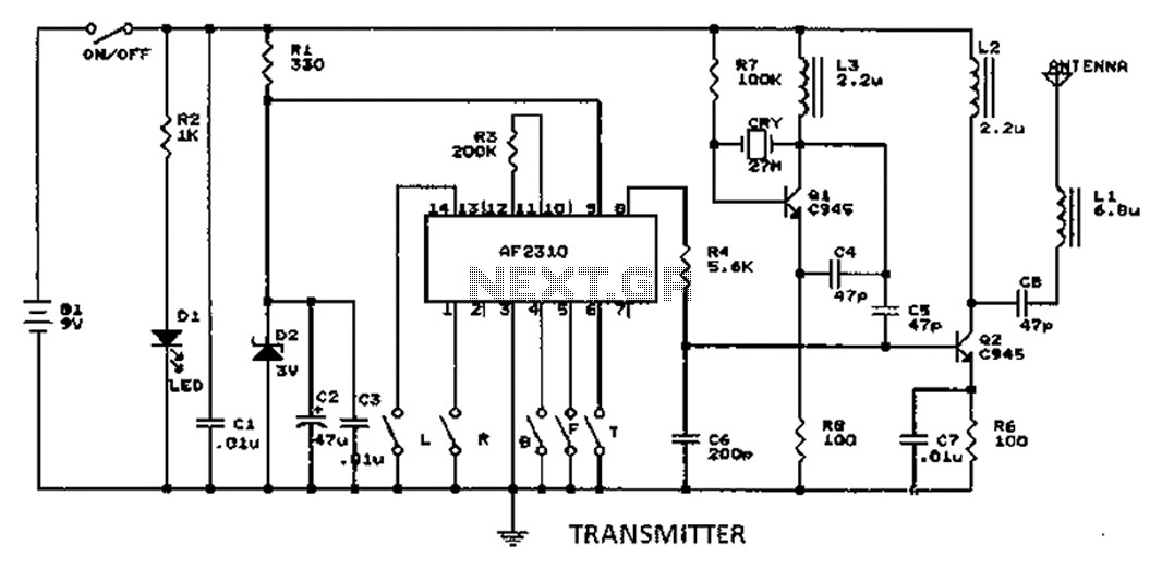
A radio control circuit designed for controlling small motors, similar to a car radio remote control toy, offers seven functions: forward, backward, left, right, left behind, right behind, and stop. The circuit requires a 27.9 megahertz frequency and a...
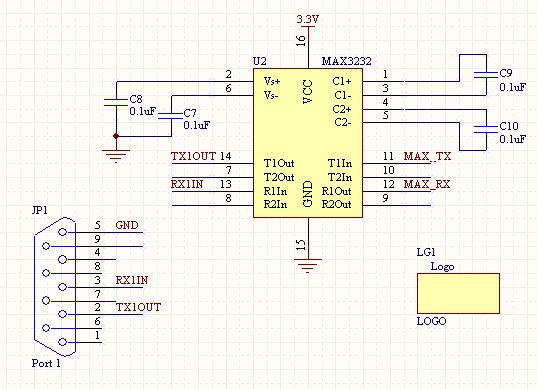
Once the setup of an RS232 connection is understood, it becomes a straightforward process for future projects. This design features a compact SMD version of the power supply, which can also be constructed using through-hole components on a breadboard....
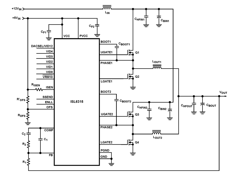
The ISL6315 two-phase PWM control integrated circuit (IC) offers a precise voltage regulation system capable of handling advanced loads ranging from 60A to 80A. Multiphase power conversion represents a significant shift from traditional single-phase converter configurations, which are increasingly...
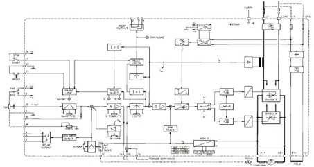
This figure represents the 4Q2 DC Motor Speed Controller Circuit Block Diagram, designed for comprehensive control of conventional shunt-wound and permanent magnet motors with a capacity of up to 75 kW, as specified in the datasheet. This type of...
The initial step often taken when learning about any microcontroller or embedded system is to make an LED blink. The circuit presented below illustrates the setup for interfacing an LED. Note: Due to the large dimensions of the circuit...
This motor speed controller utilizes a single IC, the LM1014, to regulate the speed of a DC motor. It detects the increase in motor current as the rotation of the motor increases. The motor speed controller is designed around the...