
DC Motor Speed Controller Circuit
The motor speed controller is designed around the LM1014 integrated circuit, which is a versatile operational amplifier. This IC is employed to create a feedback loop that adjusts the voltage supplied to the DC motor, thereby controlling its speed. The circuit configuration typically includes a potentiometer, which allows for manual adjustment of the reference voltage, enabling the user to set the desired speed of the motor.
The controller operates by monitoring the current flowing through the motor. As the load on the motor increases, the current rises, which is sensed by the LM1014. This increase in current is fed back to the input of the operational amplifier, which adjusts the output voltage accordingly to maintain the desired speed. The output stage of the LM1014 may be coupled with a transistor or a MOSFET to handle the higher current requirements of the motor, ensuring efficient operation.
Additional components in the circuit may include diodes for flyback protection, capacitors for filtering, and resistors for setting gain and stability. The design must ensure that the LM1014 operates within its specified voltage and current limits to prevent damage. Proper layout and thermal management are also critical, as the LM1014 and associated power components may generate heat during operation.
In summary, the motor speed controller based on the LM1014 provides an effective means of regulating the speed of a DC motor by utilizing feedback from motor current, allowing for precise control suited to various applications.This motor speed controller uses a single IC LM1014 to control the speed of a DC motor. It senses the increase in the motor-current when the rotation of th.. 🔗 External reference
Related Circuits
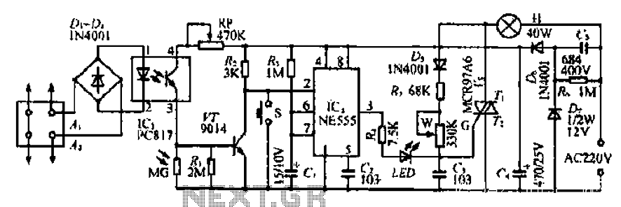
The Ai. A2 series operates with a telephone line, where sound anomalies or off-hook currents activate a light within an arc tube, which in turn triggers a photosensitive MOSFET. This process involves a saturated conduction base voltage that sends...
This circuit below shows a teleremote circuit that enables the switching on and off of appliances through telephone lines. The teleremote circuit utilizes a telephone line as a medium for controlling electrical appliances from a distance. The primary components...
IR appliances use pulses (control signals) sent over a modulated IR carrier wave. The carrier wave may be modulated at various frequencies, 36-38KHz being the most popular. Some Satellite receivers use even higher frequencies than this. The IR1 remote...
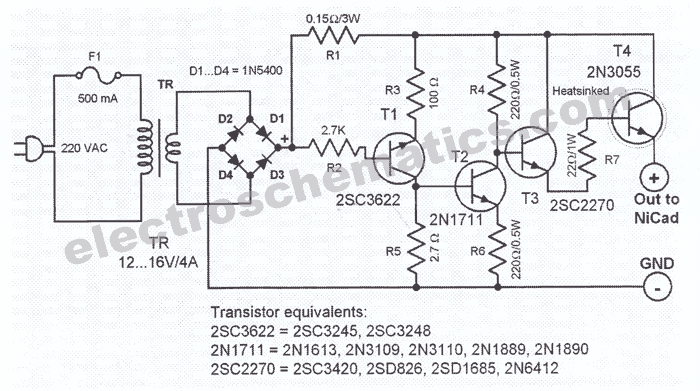
This NiCd battery charger circuit schematic can charge 6 volts as well as 12 volts NiCad batteries. It uses a transformer that can deliver 4 to 5 A current. The NiCd battery charger circuit is designed to accommodate both 6V...
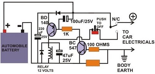
A circuit breaker is an electronic device that functions to protect an electrical circuit from hazards or damage caused by overloads or short circuits. A circuit breaker operates by automatically interrupting the flow of electricity when it detects an...
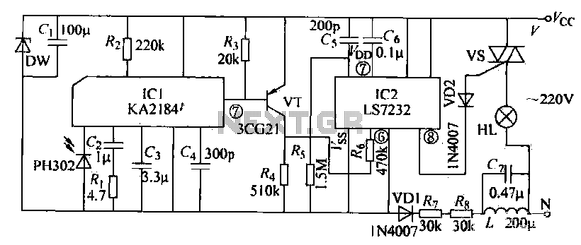
The receiving circuit operates as follows: when the infrared receiver detects a signal from the remote control transmitter, the KA2184 processes this signal, resulting in a low output at the pin. This low output is directly connected to the...