
Schematic of a Breadboard Arduino

The schematic focuses on the fundamental connections required for the ATmega328 microcontroller. It is designed to facilitate a straightforward implementation, ensuring that users can easily integrate it into their projects. The ATmega328 is a widely used microcontroller in the Arduino ecosystem, known for its versatility and ease of use.
In this schematic, the essential connections include power supply pins, ground, and the necessary programming interfaces. The microcontroller operates at a voltage typically ranging from 1.8V to 5.5V, with 5V being the standard for Arduino applications. The voltage regulation circuit, which the user must design, is crucial for maintaining a stable voltage supply to the microcontroller and its peripherals.
The AREF pin is used for providing an external reference voltage for the ADC. If the ADC functionality is not required, this pin can remain unconnected. The AVCC pin should be connected to the same voltage as the VCC pin to ensure proper operation of the ADC.
The RESET pin is essential for initializing the microcontroller. A pull-up resistor is recommended to ensure the pin remains high during normal operation, with a value between 1 kOhm and 100 kOhm being suitable. This resistor helps prevent accidental resets due to noise or interference.
The LED on pin D13 serves as a visual indicator of the microcontroller's operation. The current-limiting resistor for this LED must be calculated based on the forward voltage and current specifications of the LED, as well as the supply voltage. This ensures that the LED operates within its safe limits while providing adequate brightness.
Overall, this schematic serves as a foundation for various projects utilizing the ATmega328 microcontroller, allowing for customization and expansion based on specific project requirements.This schematic is for an extremely bare-bones circuit and includes only the needed components to operate a ATmega328 running the Arduino Uno bootloader. I leave it to you to design your voltage regulation circuit (see this post ). The connections to AREF and AVCC are only needed if you intend to use the chip`s ADC, but I included these connections anyway.
I usually turn the ADC and all of the analog pins off for my projects to save power (see this post ). The pull up resistor to the RESET pin can be any reasonable value between 1 and 100 kOhm. The value of the current limiting resistor connected to the Arduino indication LED on pin D13 should be selected to suit your system voltage and LED (see this post ).
🔗 External reference
Related Circuits

Each issue produces a specific frequency of sound, and the audio remote control will switch states based on these frequencies. The circuit is designed to detect other frequencies emitted by environmental sounds with strong anti-interference capabilities. The circuit operates...
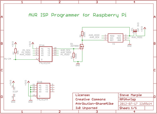
As a fully-featured Linux computer, many external programmers can be used with the Raspberry Pi to program the Atmel AVR range of microprocessors. It is also possible to utilize the general-purpose input/output lines (GPIOs) found on the Raspberry Pi...

In forward inverter system applications, the IRZ110 is used to receive a signal when the line is shown in Figure 12-39. In this application, the next channel utilizes the IR 2110 and shares an input pulse signal that determines...

This circuit can for example be incorporated into a diet to pressure warning. The meter can measure voltages from -99 mV to 999 mV. The circuit uses two ICs, the CA 3161 and CA 3162. IC1 converts the analog...

The circuit is based on the NE555 timer, functioning as a simple noise maker, with its output connected to a single transistor oscillator. This oscillator is designed to operate within a frequency range of 800 MHz to 2 GHz,...
This circuit is designed for dimming devices powered by transformer-based power supplies, specifically those operating at 12, 24, or 48 volts, rather than standard 120 volts. The project involves various components, including a soldering iron, wire strippers, breadboard or...