
arduino based remote control for electric door

The replacement remote control system for the electric garage door consists of a transmitter and a receiver, designed to communicate wirelessly. The transmitter is equipped with a microcontroller that generates a unique code each time the button is pressed, ensuring secure access to the garage. This code is transmitted via radio frequency (RF) to the receiver unit, which is connected to the garage door opener.
The receiver includes a decoder circuit that interprets the incoming RF signals. When the correct code is received, the decoder activates a relay that controls the garage door motor. The circuit is powered by a regulated power supply, which can be sourced from the garage's existing electrical system or from a dedicated battery pack to ensure reliable operation.
To enhance functionality, the system may incorporate additional features such as a rolling code mechanism to prevent unauthorized access, LED indicators to signal transmission status, and a learning function that allows the receiver to accept new transmitter codes. The components are housed in a weather-resistant enclosure to protect against environmental factors, ensuring durability and longevity.
Overall, the design of this replacement remote control system emphasizes reliability, security, and ease of use, providing an effective solution for controlling an electric garage door.I recently built a replacement remote control system for an electric garage door after the old remote had given up for the babillionth time. I`m sure the old one would have been possible to repair once again but it was 35 years old and not much fun.
Old receiver and transmitter Pictures from left to.. 🔗 External reference
Related Circuits
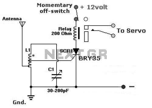
The diagram illustrates a simple and efficient receiver designed for controlling garage doors, starter motors, alarms, warning systems, and various other applications. The SCR utilized in this circuit features an exceptionally low trigger current of 30 µA. The circuit operates...
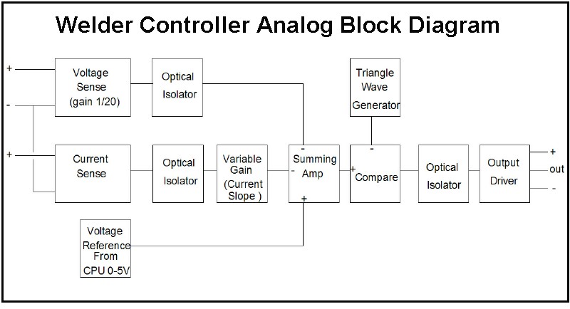
The first board is digitally controlled, while the actual welding current is analog. This design enables real-time operation without requiring the CPU to process the voltage or current. A block diagram illustrates its function: it operates as a switching...
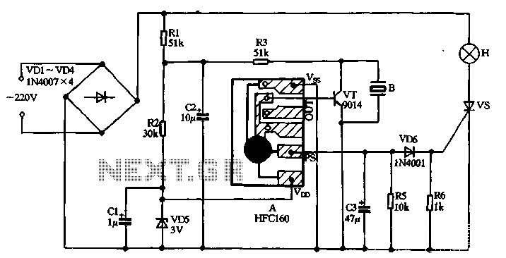
220V AC power is supplied through a VD1 to VD4 bridge rectifier and a voltage regulator circuit involving R1, R2, and VD5 components. The output provides a DC voltage of approximately 3V, which powers the manifold A. The manifold...
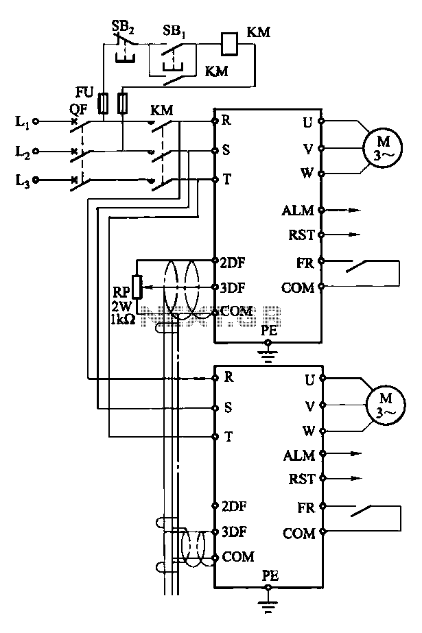
Each motor operates with an independent drive; however, only one frequency is utilized for a specific device. This setup employs a single RP potentiometer to control multiple motors in parallel. In this configuration, the circuit design allows for multiple motors to...

This is a simple hobby circuit for a remote-controlled toy car. The primary component utilized is the IR sensor circuit, which includes a TSOP IR receiver. This receiver allows the user to start and stop the DC motor of...
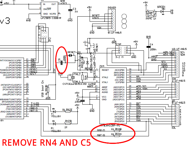
The Arduino Uno is a simple modification that bypasses the USB circuitry, allowing the device to be programmed using a serial port. The Arduino Uno is a widely used microcontroller board based on the ATmega328P microcontroller. It is designed to...