
arduino based thermorbios weather station receiver

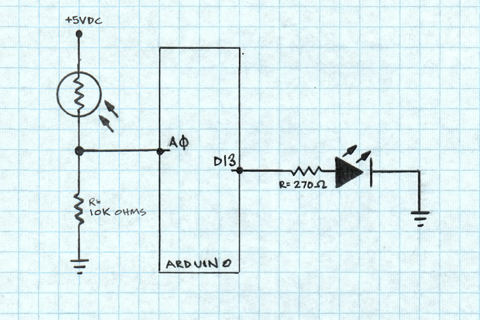
The wireless weather station receiver circuit utilizes an RF receiver module to capture weather data transmitted wirelessly. The core component of the circuit is the Arduino microcontroller, which processes the incoming RF signals. The RF receiver is connected to pin 8 of the Arduino through a 1kΩ resistor, ensuring that the signal is appropriately attenuated to protect the microcontroller's input pin from excessive current. This connection allows the Arduino to read the digital data transmitted by the weather station.
An LED is incorporated into the design, connected to pin 6 through a 330Ω resistor. This LED serves as an indicator, providing visual feedback when the Arduino receives a valid signal. The choice of a 330Ω resistor is crucial, as it limits the current flowing through the LED, preventing damage and ensuring optimal brightness.
The circuit design follows the general layout presented in the Practical Arduino schematic, with the notable exception of the LED connection on pin 7, which has been omitted in this implementation. This adaptation allows for a simplified circuit while retaining the essential functionality of the weather station receiver.
The RF signals are decoded in the Arduino's firmware, which has been developed based on extensive analysis of the signal characteristics. The development process involved using a soundcard to capture and analyze the RF signal, followed by a methodical decoding of the data packets. This step was critical in understanding the communication protocol used by the weather station, ensuring accurate data retrieval.
For those interested in replicating or modifying the project, the complete code is available on GitHub. Future enhancements and modifications are planned, as indicated by a small to-do list, which will be addressed at a later date. This project exemplifies a practical application of wireless communication and microcontroller integration in weather monitoring systems.Have finished documenting/cleaning the code for my Jaycar el-cheapo Thermor/BIOS branded wireless weather station receiver. The basis for the code comes from the Practical Arduino weather station receiver project. In the end all it took was a week of analysing the RF signal from the weather station using my soundcard and wasting countless hours decoding the packets!
And a little determination. Receiving the signal i s pretty straight forward an RF receiver is connected to pin 8 of the arduino via a 1k resistor, and an LED via a 330ohm resistor to pin 6. See the Practical Arduino schematic for more info it is essentially the same circuit, just minus the LED on pin 7.
I have uploaded the sketch to github: for anyone else to try. There is a small to-do list for me to complete, but that can happen later. 🔗 External reference
Related Circuits

The Command Transmitter-Receiver (A3023) is designed to test the command receiver proposed for the Implantable Sensor with Lamp (ISL) in the conceptual design phase. The A3023 consists of two primary components: the Command Transmitter section, which features a 146-MHz...
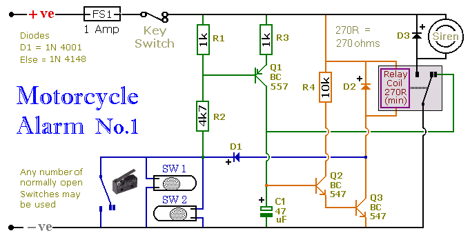
This circuit includes a timed output and an automatic reset feature. It can be manually operated using a key switch or a concealed switch. By incorporating an external relay, the circuit will automatically engage or immobilize the machine each...
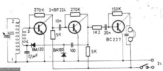
Oscillating circuits (coils) are constructed on a ferrite bar. For long wave reception, winding "1-2" consists of 135 turns, while winding "3-4" consists of 20 turns. For medium wave reception, winding "1-2" has 75 turns, and winding "3-4" has...

Aircraft communication is still AM modulated and the frequency is about 110-125 MHz. What differs this construction from my two previous is that I have implemented many blocks into one circuit and therefore I will have superior performance with...
A project is underway to determine the number of sun hours available at a specific location and to track this data over time as part of solar power installation design. The concept involves utilizing a light detector exposed to...
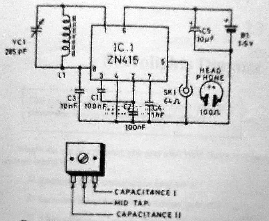
The circuit utilizes an 8-pin DIP ZN415 radio receiver chip manufactured by Ferranti. This circuit offers advantages over the ZN414 model by incorporating an integrated amplifier stage. The integrated circuit (IC) features a complete AM detection subsystem. It employs...