
Command Transmitter-Receiver
The Command Transmitter-Receiver (A3023) serves as a critical component in the testing and operation of the ISL system. The device's architecture consists of two main sections: the Command Transmitter (A3023CT) and the Command Receiver (A3023CR). The A3023CT's VCO operates at 146 MHz, which is modulated to transmit commands effectively. The RF amplifier enhances the signal strength, while the RF switches allow for the modulation of the amplitude, ensuring that the output can be adjusted to the required levels for reliable communication.
The BNC output serves as a standard interface for RF power transmission, while the LWDAQ device socket facilitates control of the RF switches and power management of the amplifier. The ability to modulate the VCO through a 5-V triangle wave input enables precise frequency control, essential for various experimental setups. The implementation of the blue indicator lamp serves as a visual confirmation of RF power activation, enhancing user feedback during operation.
The A3023CT's capability to drive antennas, especially with the integration of a 2-dB attenuator, ensures that the RF output remains stable even when interfacing with variable loads such as antennas. This feature is crucial for testing the performance of the Implantable Lamp (A3024A), enabling effective stimulation at predetermined distances. The inclusion of a booster amplifier and a telescoping antenna further extends the operational range, making the device suitable for various experimental conditions.
The Command Receiver (A3023CR) complements the transmitter by providing essential feedback and control capabilities. Its design allows for straightforward integration with power sources and command inputs, facilitating testing of the ISL crystal diode receiver. The presence of indicator LEDs provides immediate visual feedback regarding the status of the power detector output, enhancing usability.
Overall, the A3023 system is designed to provide a robust testing platform for implantable sensor technologies, with flexible configurations and comprehensive control features that support a variety of experimental applications.The Command Transmitter-Receiver (A3023) is intended to test the command receiver we propose for the ISL (Implantable Sensor with Lamp) in our Conceptual Design. The A3023 is a LWDAQ Device in two parts. The Command Transmitter section contains a 146-MHz (2-m band) VCO, RF amplifier, and RF switches to provide 100% amplitude modulation.
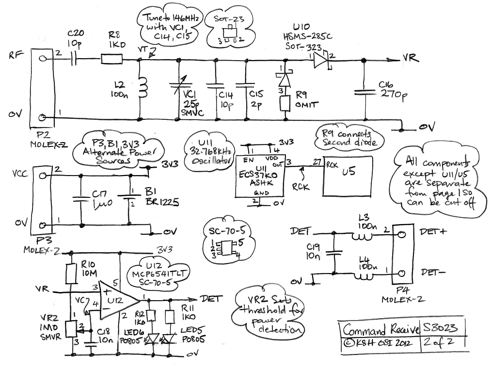
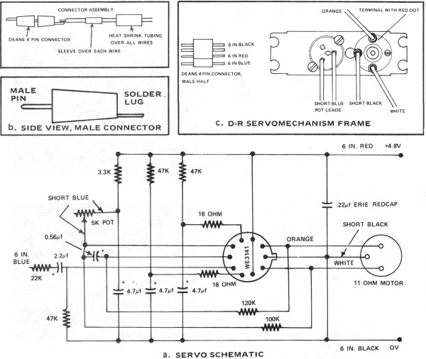
The Comm and Receiver section contains a tuner circuit, a demodulator, a comparator, and two indicator lamps. Figure: Command Transmitter (A3023CT) in Enclosure. ON is a blue lamp that indicates when the RF power is on. POWER is a green lamp indicated circuit power is connected. RUN is a yellow lamp that indicates a stimulus program is running. INTERVAL is a re lamp that flashes at the end of a stimulus interval. The Command Transmitter (A3023CT) provides a BNC output for its RF power, and a LWDAQ device socket through which we can control the two RF switches and power to the RF amplifier. It provides a BNC input to modulate its VCO. By applying a 5-V triangle wave to the SWEEP input, the A3023CT will provide a near-linear sweep of 146 ±50 MHz.
The A3023CT responds to LWDAQ commands with the same interface as the Lamp Controller A2060L, so that it`s 146-MHz power output flashes on and off just as a lamp would flash on and off. The blue indicator lamp on the A3023CT flashes to indicate the RF power is on. Figure: Command Transmitter (A3023CT) with Flexible Antenna. Here we see the A3023CT driving an antenna through a 2-dB attenuator, and stimulating an Implantable Lamp (A3024A).
The 2-dB attenuator is necessary to stabilize the A3023CT power amplifier when driving a poorly-behaved load like an antenna. This arrangement supplies 100 mW (20 dBm) of 146 MHz RF power to the antenna, and is useful for testing Implantable Lamp circuits.
Figure: Command Transmitter (A3023CT) with Booster Amplifier and Telescoping Antenna. Here we see the A3023CT driving a ZHL-3A+ booster amplifier through a 12-dB attenuator. The attenuator is necessary to avoid over-driving the input of the ZHL-3A+. The booster amplifier drives a half-wave telescoping antenna directly. This arrangement supplies 1. 6 W (32 dBm) of 146 MHz RF power to the antenna, and is effective at stimulating Implantable Lamps at ranges 1 m (100% reliable) to 6 m (50% reliable). The Command Receiver (A3023CR) provides two-pin connectors for RF input, 3-V power, and binary power detector output.
We can solder a battery to the board directly if we like, in place of B1. The A3023CR is an experimental circuit designed to test the ISL crystal diode receiver design. Figure: Command Receiver. Circuit power is supplied by a battery through the connector on the lower left. The RF command signal enters through the connector on the upper left. Two blue LEDs, one on the top and one on the bottom of the board, indicate when the power detector output is HI. Here is a list of variations and accessories for the A3023. For stimulation of implantable lamps, we use the Command Transmitters (A3023CT), a 12-dB attenuator, a 30-cm coaxial cable, a booster amplifier, and a half-wave 146-MHz antenna.
[03-OCT-12] We adapt the A2075 firmware for the A3023. The LWDAQ Command receiver uses a ring oscillator to decode the serial commands arriving from the driver. The 32. 768 kHz oscillator, U11, provides RCK for transmission timing. The logic chip provides 256 programmable logic gates for future applications. The P3023A01 firmware allows us to close switches X and Y individually with the LWDAQ command bits DC1 and DC2 respectively.
Thus we can determine the isolation of each switch individually and together. [14-DEC-12] The P3023A02 sets up the Command Transmitter as a Lamp Controller ( A2060L ). The pulse timing is driven by the A3023`s 32. 768-kHz clock instead of the 40-MHz clock used on the A2060L. Now we can control the A3023 with the Lamp Controller Tool. By setting the pulse time to 10 ms and the pulse interval 🔗 External reference
Related Circuits
The electric fan with remote control underwent extensive research and development in the Pearl River Delta area of Guangdong during the early 1990s. It utilizes a specialized mask chip that serves as the primary management chip. A systematic scheme...
Xpressnet is a bus system designed for model railways, facilitating the interconnection of input devices, computer interfaces, stationary decoders, and feedback detectors. Numerous commercial input devices, such as the multi-mouse from Roco, utilize this bus system. An adapter is...
The infrared transmitter and receiver circuit depicted in the schematic diagram can function as a remote control system. The transmitter operates as an oscillator circuit, with the frequency adjustable through the R1 potentiometer (or trimmer pot). This oscillation ensures...

The infrared transmitter and receiver circuit depicted in the schematic diagram can function as a remote control. The transmitter operates as an oscillator circuit, with the frequency adjustable via the R1 potentiometer (or trimmer pot). This oscillation ensures that...
Part II of the AAM Commander RC System Article, scanned from the May 1972 edition of American Aircraft Modeler. The AAM Commander RC System is a sophisticated radio control system designed for model aircraft, providing enhanced control and performance for...
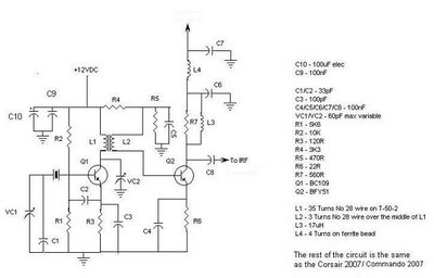
This document provides information about the Corsair and Commando Transmitters designed by Dave Martin of WNKR. It outlines the construction of each transmitter and includes examples created by others. The circuit diagram presented illustrates the initial two stages of...