
Arduino Blink

To construct the described circuit, the following components and steps are essential:
1. **Components Required:**
- Arduino board (e.g., Arduino Uno)
- 1 x 220-ohm resistor
- 1 x LED (Light Emitting Diode)
- Jumper wires
- Breadboard (optional for prototyping)
2. **Circuit Assembly:**
- Connect one terminal of the 220-ohm resistor to digital pin 13 on the Arduino board. This pin is often designated for simple output tasks and is commonly used for basic LED projects.
- Attach the anode (long leg) of the LED to the free end of the resistor. This connection allows the LED to receive current when the pin is set to HIGH.
- Connect the cathode (short leg) of the LED directly to the ground (GND) pin on the Arduino. This completes the circuit and provides a return path for the current.
3. **Programming the Arduino:**
- Once the circuit is completed, connect the Arduino board to a computer using a USB cable. Open the Arduino IDE (Integrated Development Environment) to write and upload the code.
- The basic code for blinking the LED is as follows:
```cpp
void setup() {
pinMode(13, OUTPUT); // Set pin 13 as an output
}
void loop() {
digitalWrite(13, HIGH); // Turn the LED on
delay(1000); // Wait for one second
digitalWrite(13, LOW); // Turn the LED off
delay(1000); // Wait for one second
}
```
4. **Functionality Explanation:**
- In the setup() function, pin 13 is configured as an output pin. This setup is crucial for controlling the LED.
- The loop() function continuously executes the code within it, turning the LED on and off at one-second intervals. The digitalWrite() function is used to set the pin state to HIGH (on) and LOW (off).
- The delay() function pauses the execution for the specified duration, allowing the LED to remain in each state long enough for human observation.
5. **Additional Considerations:**
- It is advisable to test the circuit with the built-in LED before adding external components. The Arduino board typically has an LED connected to pin 13, which will blink according to the uploaded code.
- For more advanced timing control, the BlinkWithoutDelay example can be utilized. This example demonstrates how to manage multiple tasks concurrently without blocking the execution of the program, allowing for more complex applications and interactions.
This circuit serves as an excellent introduction to basic electronics and programming with Arduino, providing a practical demonstration of how to control outputs using simple code and circuit design.To build the circuit, attach a 220-ohm resistor to pin 13. Then attach the long leg of an LED (the positive leg, called the anode) to the resistor. Attach the short leg (the negative leg, called the cathode) to ground. Then plug your Arduino board into your computer, start the Arduino program, and enter the code below. Most Arduino boards already have an LED attached to pin 13 on the board itself. If you run this example with no hardware attached, you should see that LED blink. That takes pin 13 back to 0 volts, and turns the LED off. In between the on and the off, you want enough time for a person to see the change, so the delay() commands tell the Arduino to do nothing for 1000 milliseconds, or one second. When you use the delay() command, nothing else happens for that amount of time. Once you`ve understood the basic examples, check out the BlinkWithoutDelay example to learn how to create a delay while doing other things.
🔗 External reference
Related Circuits
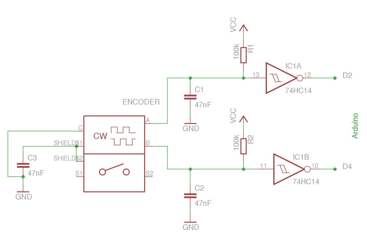
The example circuit and code should be sufficient to begin without delving into additional details. A rotary encoder is an electromechanical component with a shaft that records rotation and converts it into electrical pulses to indicate the direction of...
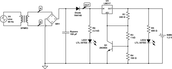
An Arduino powered by 2 or 4 rechargeable NiMH AA batteries is being developed. The choice of using two batteries is based on the intention to boost the voltage to meet the requirements. The main challenge is ensuring that...
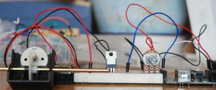
A quick circuit showing how to control the speed of a DC motor with a potentiometer with your Arduino board. Also shows how to use a TIP120 transistor to allow the Arduino control a larger power supply. This circuit utilizes...
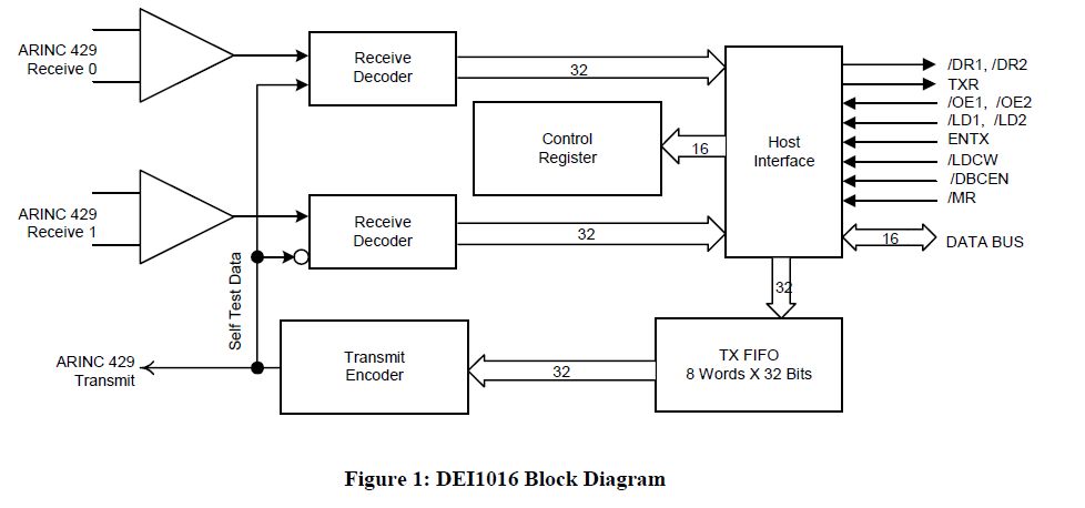
This document outlines the process of interfacing an Arduino with an ARINC 429 transceiver, illustrating the general methodology for connecting an Arduino to electronic circuits that can be applied to individual designs. The ARINC 429 bus is the predominant...
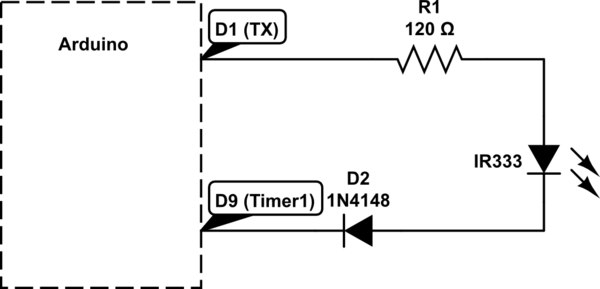
Utilizing a digital infrared (IR) receiver module and a digital IR transmitter module, each connected to separate Arduino Uno boards, the objective is to transmit data, such as "1234", to the receiver and display this data on an LCD....
The text of the Arduino reference is licensed under a Creative Commons Attribution-ShareAlike 3.0 License. Code samples in the reference are released into the public domain. The Arduino platform is an open-source electronics prototyping environment that enables users to create...