
Arduino board
Creating a custom Arduino board can be an enriching project that allows for greater flexibility and personalization in electronic designs. The process typically involves using a microcontroller, such as the ATmega328P, which is the same chip used in the Arduino Uno.
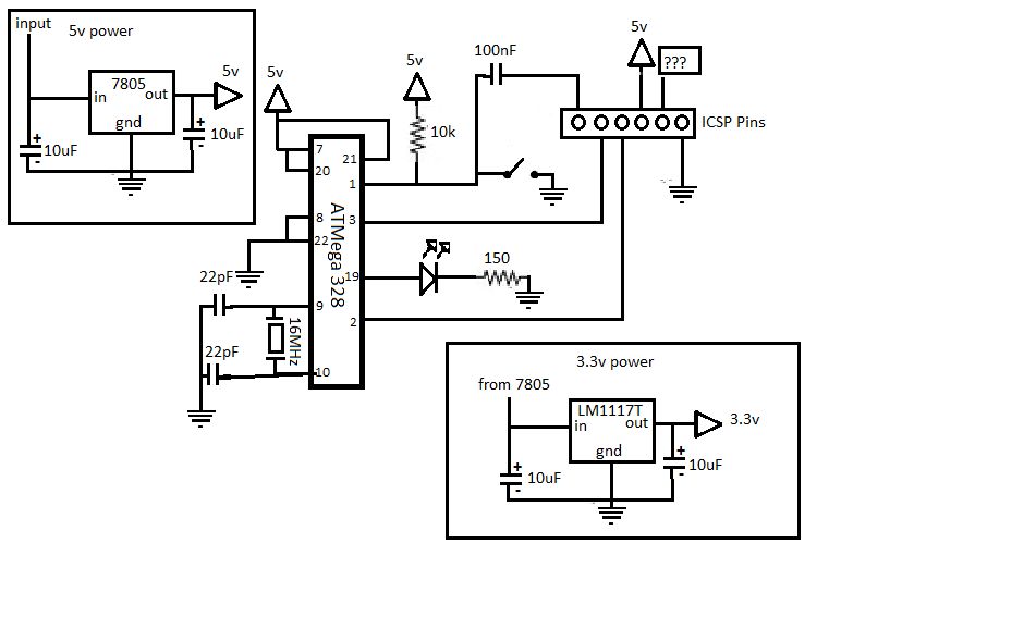
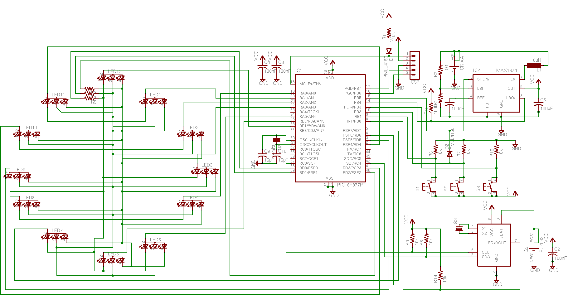
To begin, a schematic is required that outlines the connections between the microcontroller and essential components. The schematic should include the following elements:
1. **Microcontroller**: The ATmega328P should be placed at the center of the design. Ensure that the appropriate power supply pins are connected to a voltage regulator to provide a stable 5V output.
2. **Power Supply**: Include a barrel jack or USB connector for powering the board. A voltage regulator, such as the LM7805, can be used to step down the voltage to 5V. Capacitors (typically 10µF and 100nF) should be placed near the power pins of the microcontroller to filter noise and stabilize the voltage.
3. **Clock Source**: Connect a 16 MHz crystal oscillator to the XTAL1 and XTAL2 pins of the microcontroller. Additionally, load capacitors (usually 22pF) should be connected from each pin of the crystal to ground to ensure proper oscillation.
4. **Reset Circuit**: Incorporate a reset button connected to the RESET pin of the microcontroller. A pull-up resistor (10kΩ) should also be connected between the RESET pin and the power supply to keep the microcontroller in a ready state.
5. **Digital and Analog I/O**: Designate pins for digital input/output and analog input. Include headers for connecting external devices, such as sensors or actuators. Each I/O pin should be connected to a 1kΩ resistor to protect the microcontroller from potential overcurrent.
6. **Programming Interface**: Provide a programming interface, typically an ICSP (In-Circuit Serial Programming) header, for uploading sketches to the microcontroller. This should include connections for MISO, MOSI, SCK, RESET, VCC, and GND.
7. **LED Indicators**: Optionally, add an LED connected to one of the digital pins to serve as a power indicator or status light. A current-limiting resistor (220Ω) should be used in series with the LED to prevent damage.
Once the schematic is complete, a printed circuit board (PCB) can be designed using software tools such as Eagle or KiCad. After fabricating the PCB, components can be soldered onto the board, and the custom Arduino board will be ready for use in various projects, offering a tailored solution for specific applications.If your are like me which I am guessing you are, then ever since you got into doing stuff with arduino you have wanted to make your own arduino board.. 🔗 External reference
Related Circuits
Acoustic check of transistor and diode junctions. Also suitable as a continuity tester. Short circuits or broken PCB tracks can be easily recognized. The acoustic check of transistor and diode junctions is a method used to assess the functionality of...
A keyboard is a fundamental component of an embedded or microcontroller system. For small-scale and hobby projects, a 4x4 (hex) matrix keyboard is adequate. The keys in the matrix keyboard are arranged in a matrix configuration to efficiently utilize...
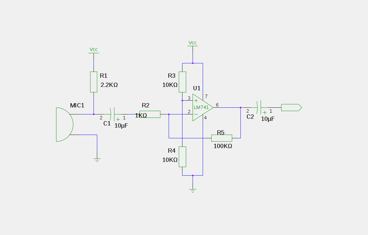
An electret microphone has been connected to an operational amplifier (op-amp), with the output directed to an Arduino microcontroller. The analog-to-digital converter (ADC) on the microcontroller converts a voltage range of 0 to 5 volts into a 10-bit number,...
The doorbell button was replaced with a lighted version, but the chime continued to sound after the button was pressed. These lighted buttons incorporate an incandescent bulb in parallel with the button, a component that has been modified in...
A 5V power supply is used to function as a switch controlled by an Arduino. Direct control from the Arduino pin is not feasible because most general-purpose relays require a minimum of 150mW to activate, which translates to over...
A simple RS232 example project that draws all its power from the serial port. It is designed to power a microcontroller and facilitate communication between the serial port and the microcontroller. This project utilizes the capability of PC serial...
Warning: include(partials/cookie-banner.php): Failed to open stream: Permission denied in /var/www/html/nextgr/view-circuit.php on line 713
Warning: include(): Failed opening 'partials/cookie-banner.php' for inclusion (include_path='.:/usr/share/php') in /var/www/html/nextgr/view-circuit.php on line 713