
Replacing the driver board in an old-school door chime
The described circuit involves a doorbell system where the traditional button has been substituted with a lighted variant. This modification introduces an incandescent bulb connected in parallel with the button mechanism. When the button is pressed, it not only completes the circuit to activate the chime but also illuminates the bulb.
The issue observed, where the chime continues to sound after the button is released, suggests a potential design flaw or misconfiguration in the circuit. Typically, a standard doorbell circuit consists of a transformer, a chime, and a momentary switch (the button). When the button is pressed, it allows current to flow from the transformer to the chime, producing sound.
In this case, the inclusion of the incandescent bulb in parallel may create a path that keeps the circuit closed even after the button is released. The bulb, when energized, could be causing a feedback loop or a delay in the circuit returning to its open state, maintaining the chime's operation.
To resolve this issue, it is advisable to review the circuit design. One potential solution is to incorporate a relay or a capacitor that can momentarily hold the circuit closed but will eventually open after a short delay, allowing the chime to stop once the button is released. Additionally, ensuring that the button itself is a momentary switch is crucial, as a latching switch could also lead to continuous chime activation.
Overall, careful analysis of the circuit components and their configuration is necessary to ensure proper operation of the lighted doorbell button without unintended chime activation.replaced their doorbell button with one that lights up and found that the chime wouldn`t stop sounding after the button was pushed. These lighted buttons use an incandescent bulb in parallel with the button (a piece of hardware we`ve hacked in the past)..
🔗 External reference
Related Circuits
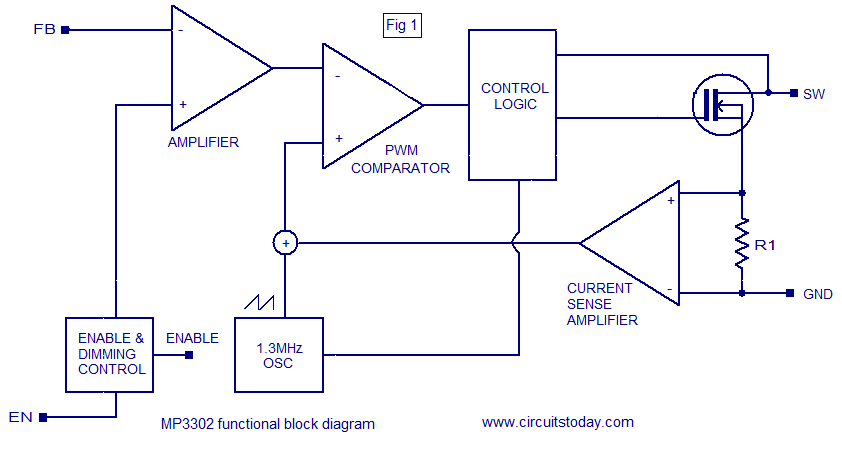
The MP3302 is a boost converter integrated circuit (IC) specifically designed for LED drive applications. It is capable of driving 27 LEDs, arranged as 9 strings of 3 white LEDs in series, powered by a lithium-ion battery. The IC...

A DC brush motor driver circuit diagram utilizing the MC33035 chip is presented, illustrating a typical configuration for driving a straight DC brush motor. The circuit incorporates a field-effect transistor (FET) bridge driver setup. When transistor VT3 is activated,...
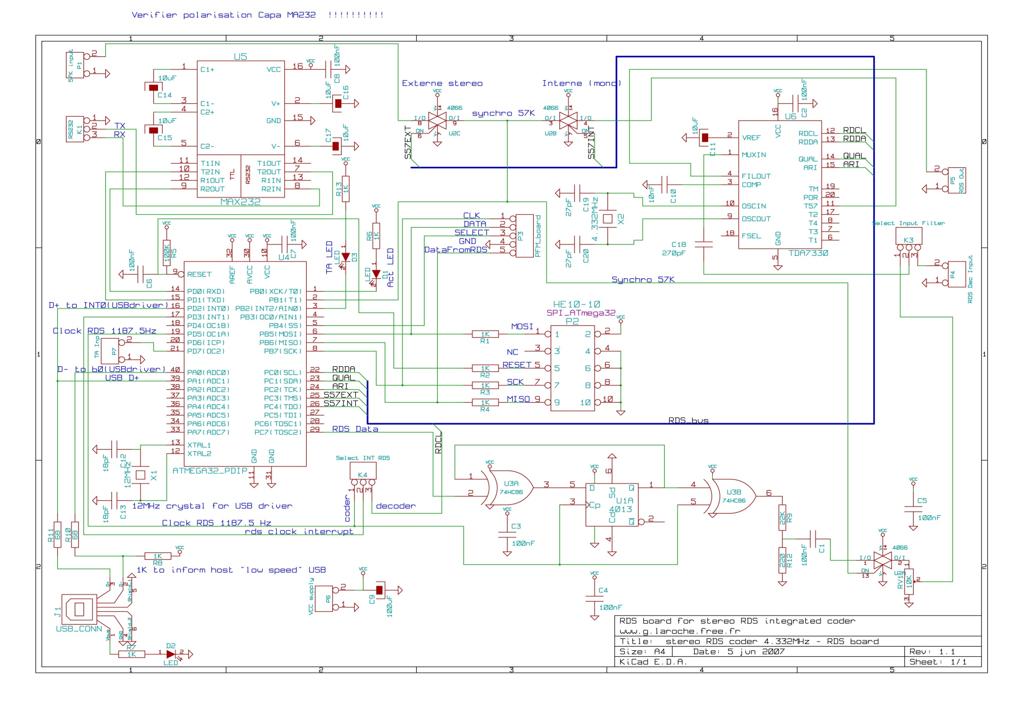
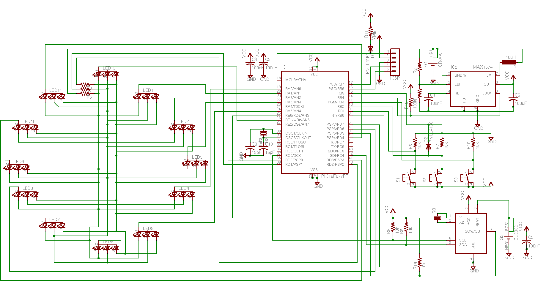
This board is an RDS coder utilizing an ATMEL AVR ATmega32 microcontroller. It can be controlled via an RS232 link, USB interface, or SPI. TA data is displayed with an LED and can be controlled through hardware input, RS232,...
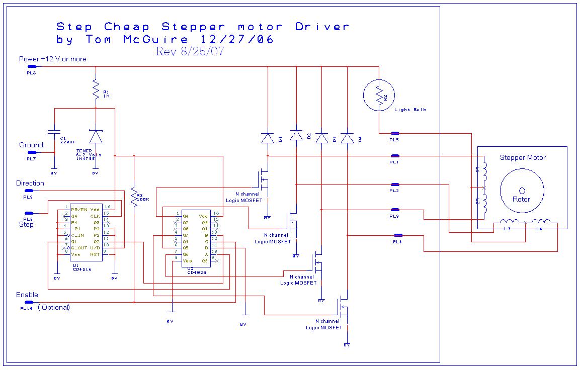
This circuit is designed to work with a variety of stepper motors, specifically 5 or 6 wire unipolar types. It operates within a voltage range of approximately 9 volts to 24 volts. A breadboard layout of the circuit is...

This design was created to address a challenge with the tailwheel doors of the P-51 Mustang. The issue arises from the complex undercarriage sequence, which would necessitate two independent sequencers. The closing sequence involves the main gear doors opening,...

The L293 is designed to provide bidirectional drive currents of up to 1 A at voltages ranging from 4.5 V to 36 V. The L293D variant is capable of delivering bidirectional drive currents of up to 600 mA at...