
arduino Selecting the right relay

To implement this circuit, the following components are necessary: an NPN transistor (e.g., 2N2222 or BC337), a diode (e.g., 1N4001), and resistors (R1 and R_pullup). The NPN transistor acts as a switch, allowing the control of the ATX power supply through the Arduino. The base of the transistor is connected to the Arduino output pin through R1, while the emitter is grounded. The collector is connected to the PC_ON wire of the ATX power supply. The pull-up resistor (R_pullup) connects the PC_ON wire to the +5V supply, ensuring that the ATX power supply remains off when the Arduino output pin is low.
When the Arduino output pin is set to HIGH, current flows through R1 into the base of the NPN transistor, turning it on and allowing current to flow from the collector to the emitter. This action grounds the PC_ON wire, effectively turning on the ATX power supply. The diode is placed in reverse parallel with the load to protect against back EMF when the transistor is switched off, ensuring circuit integrity.
This configuration is efficient for low-power applications, where isolation is not a primary concern. However, for designs requiring electrical isolation, an optocoupler should be considered, as it provides better protection for the Arduino and other components from potential voltage spikes or noise from the ATX power supply. Overall, this circuit exemplifies a practical approach to controlling a power supply using an Arduino, balancing simplicity and functionality.A 5v power supply to act just like a switch. I will be controlling it with an Arduino like described here: You won`t be able to drive it directly from the Arduino pin, as most general purpose relays require at least 150mW to switch which is >30mA @ 5V. You will need to use something like this: The NPN can be just about any general purpose NPN (2N2222, BC337, etc) and the diode can be most general purpose diodes
(1N4001 or similar) VCC is your +5V. If you go to somewhere like Farnell, and use the parametric search to narrow down you options, you will get hundreds of choices, here is an example search with 5VDC general purpose relays capable of >10A and >250VAC selected. It seems this is to turn an ATX supply on by pulling the PC_ON (usually green) connection to ground. In this case the relay is a bit overkill, and a simple open collector NPN transistor circuit can be used: The dotted area is inside the PC, so all you need is the NPN transistor (almost any general purpose will do) and the resistor (4.
7kOhm is shown, but depending on the transistor gain, R1 can be between say, 50kOhm and 1kOhm - between 1kOhm and 10kOhm should work with just about anything though) The R_pullup of 1kOhm is assuming about the worst case - it will probably be between 2kOhm and 10kOhm. The circuit as shown would work with a pullup down to around 100 ohms though if needed. the thing im switching on is a atx computer PSU, to turn it on you just bridge a certain wire to a ground wire, a relay could do this yes lewis denny Aug 6 `12 at 13:45 Yes, a relay could do this.
If you are referring to the green power on signal connection, since the current is very low you could do this with just the transistor itself (the Arduino would not be isolated from the ATX in this case, but that may not be an issue) Oli Glaser Aug 6 `12 at 14:26 The ATX 2. 2 spec does not give a value for the pullup resistor, only that it is attached to +5V (see page 21). It`s probably safish to assume it`s not less than 1k, which would give 5V / 1kOhm = 5mA max. Since it`s pulled up to +5V, at 5mA you could drive it from the Arduino pin, but I`d use the transistor (or relay if you want to have things isolated) anyway just in case.
Oli Glaser Aug 6 `12 at 14:39 So would a transistor be just as safe as a relay, it`s not like there will be any power surges though the line or anything lewis denny Aug 6 `12 at 21:25 Yes the transistor will be perfectly safe to handle this, the only difference is the relay would provide isolation between the Arduino and the ATX, but if you don`t need that then use the transistor. The ATX outputs are isolated (from the HV mains side by a transformer) anyway. In fact if you did need isolation, you would be better to use an optocoupler anyway for such a small load, the relay would be overkill.
Oli Glaser Aug 6 `12 at 21:35 🔗 External reference
Related Circuits
The physical location of the compressor relay is needed, as well as instructions on how to test the pressure sensor on the plastic tank of the compressor assembly. The exact location of the relay has not been confirmed, but...
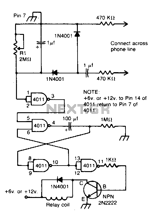
Connected across the bell circuit of a phone, this circuit activates a relay when the phone is ringing. It can utilize delay contacts to operate any bell, siren, buzzer, or lamp. The described circuit functions as a relay activation mechanism...
A cat deterrent system utilizing an Arduino, similar to existing models. Detection has been successfully implemented, and it has been determined that an ultrasonic transducer is required to generate the necessary deterrent sound. The proposed cat deterrent system employs an...
A clock-controlled relay, also known as a time delay relay, allows for the automatic activation of a load, such as a water pump, at a predetermined time. This device utilizes a standard clock mechanism to trigger the circuit, enabling...
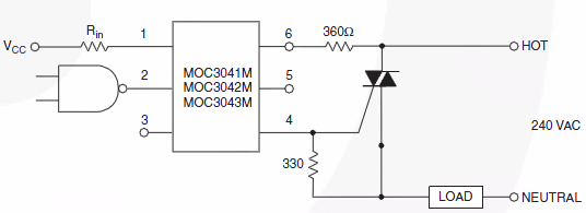
Switch 50V AC voltage. The maximum current drained will be 5A, with a frequency of 50Hz. The switching speed is not critical and can be slow, which is acceptable for the application. Initially, a solid-state relay (SSR) was considered...
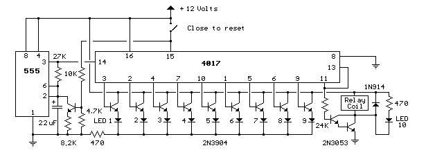
This circuit provides a visual 9-second delay using 10 LEDs before closing a 12-volt relay. When the reset switch is closed, the 4017 decade counter resets to the 0 count, illuminating the LED driven from pin 3. The 555...