
Arduino Button

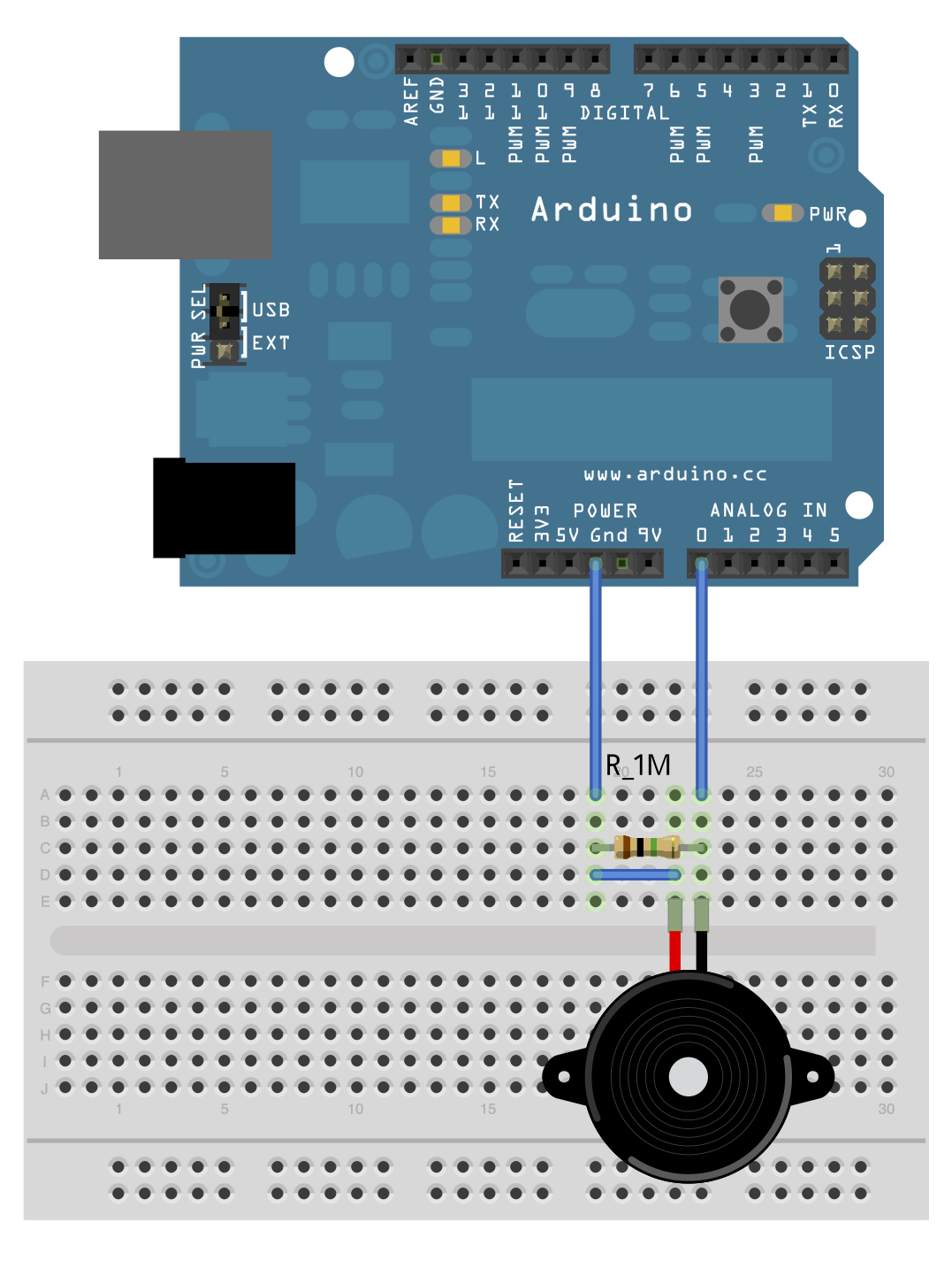
The circuit design involves connecting three wires to an Arduino board, facilitating the control of a pushbutton switch. The red wire is typically used to connect to the positive 5-volt supply, while the black wire connects to the ground (GND). These wires are routed to the vertical power rails on the breadboard, which distribute the voltage and ground throughout the circuit.
The third wire, connected to digital pin 2 on the Arduino, interfaces with one terminal of the pushbutton. The opposing terminal of the pushbutton is connected directly to the 5-volt supply, ensuring that when the button is pressed, the circuit is completed, allowing current to flow. A 10 KOhm pull-down resistor is connected from the same terminal of the pushbutton to ground. This configuration ensures that when the button is not pressed, the digital pin reads a LOW state because the resistor pulls the voltage down to ground level.
When the pushbutton is pressed, it creates a direct connection between the 5-volt supply and the digital pin, resulting in a HIGH reading. This behavior can be inverted by using a pull-up resistor instead, which would keep the input HIGH under normal conditions and switch to LOW when the button is pressed. This alternative configuration allows for flexibility in programming the behavior of the connected LED or other output devices.
It is crucial to avoid leaving the digital pin floating, as this can lead to unpredictable behavior in the circuit, such as erratic blinking of the LED. Implementing the pull-down or pull-up resistor stabilizes the input signal, ensuring reliable operation of the pushbutton interface within the Arduino project.Connect three wires to the Arduino board. The first two, red and black, connect to the two long vertical rows on the side of the breadboard to provide access to the 5 volt supply and ground. The third wire goes from digital pin 2 to one leg of the pushbutton. That same leg of the button connects through a pull-down resistor (here 10 KOhms) to grou nd. The other leg of the button connects to the 5 volt supply. When the pushbutton is open (unpressed) there is no connection between the two legs of the pushbutton, so the pin is connected to ground (through the pull-down resistor) and we read a LOW. When the button is closed (pressed), it makes a connection between its two legs, connecting the pin to 5 volts, so that we read a HIGH.
You can also wire this circuit the opposite way, with a pullup resistor keeping the input HIGH, and going LOW when the button is pressed. If so, the behavior of the sketch will be reversed, with the LED normally on and turning off when you press the button.
If you disconnect the digital i/o pin from everything, the LED may blink erratically. This is because the input is "floating" - that is, it will randomly return either HIGH or LOW. That`s why you need a pull-up or pull-down resistor in the circuit. 🔗 External reference
Related Circuits
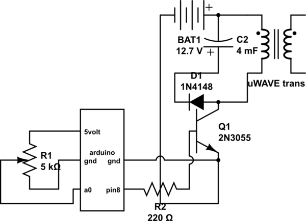
If both devices need to be powered from the battery, should the emitter be connected to the ground of the Arduino and the battery to prevent current from flowing through the Arduino ground, ensuring a clean pulse? Alternatively, can...
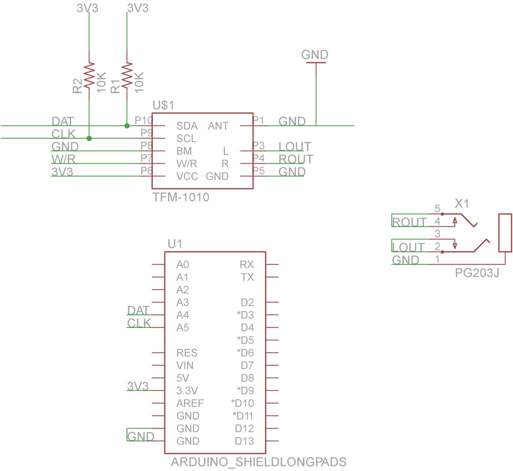
This guide will demonstrate how to construct a custom FM radio receiver shield compatible with an Arduino board. The radio chip utilized in this project is the AR1010, which can be sourced from Sparkfun or Electrokit. Code for initializing...
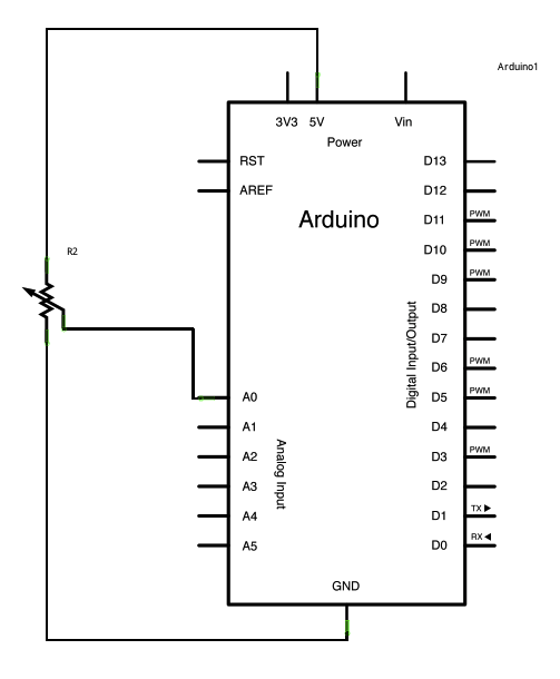
A potentiometer is a simple knob that provides variable resistance, which can be read into the Arduino board as an analog value. In this example, a potentiometer is connected to one of the Arduino's analog inputs to control the...
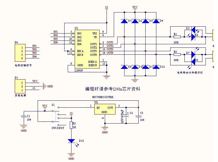
The L298N driver module incorporates the ST L298N chip, commonly utilized to drive two DC motors with voltage ratings between 3V and 30V. It features a 5V output interface that provides power for 5V single-chip circuitry and supports 3.3V...
Posts about a tutorial written by Harandi and Amirsab. The content refers to a series of instructional posts focused on a particular tutorial authored by individuals identified as Harandi and Amirsab. These posts likely encompass various topics related to electronics,...
This example demonstrates a technique for calibrating sensor input. The Arduino takes sensor readings for five seconds during startup and tracks the highest and lowest values obtained. These sensor readings during the first five seconds of the sketch execution...