
L298N Stepper Motor Driver Controller Board for Arduino

The L298N motor driver module is a robust and versatile device designed to control the operation of DC motors in various applications, including robotics and automation systems. The L298N chip operates as a dual H-bridge, allowing for bidirectional control of two DC motors. Each motor can be driven independently, enabling complex motion control scenarios.
The module can handle motor supply voltages ranging from 3V to 30V, making it suitable for a wide range of DC motors. The onboard 5V output can be used to power microcontroller units (MCUs) or other peripheral devices, ensuring that the entire system can be powered from a single source. The L298N is compatible with 3.3V MCUs, which broadens its applicability in modern electronics projects.
The control of the motors is achieved through the use of input pins that determine the direction and speed of the motors. By varying the PWM (Pulse Width Modulation) signal applied to the enable pins, the speed of the motors can be adjusted, while the direction can be controlled by setting the appropriate input pins high or low. This allows for precise control of motor functions, essential in applications requiring accurate movement.
The module is typically equipped with heat sinks to dissipate heat generated during operation, ensuring reliable performance under load. It is important to consider the current ratings of the motors and to ensure that the total load does not exceed the maximum current capacity of the L298N chip, which is rated for up to 2A per channel.
For those implementing the L298N module in their designs, schematics and detailed manuals are often provided by manufacturers, which can assist in integrating the driver into various projects. These resources outline the pin configurations, electrical characteristics, and example circuits to facilitate effective utilization of the module.The L298N driver module contains the ST` L298N chip, ususlly used to drive two 3-30V DC motor, there is a 5V output interface, power for 5V single-chip circuitry, support 3. 3VMCU control. With it, you can control the DC motor easily. You can get the diagram and manual on: 🔗 External reference
Related Circuits
Electric motors have been widely used for motion control, and various types of motor controllers have been designed to provide variable speed drives for these motors. Electric motors are integral to numerous applications requiring precise motion control, ranging from industrial...
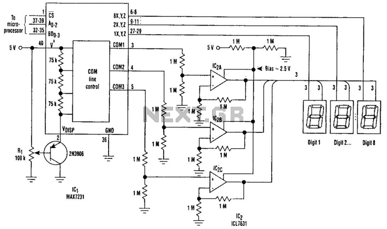
Large LCD devices with one or more displays exhibit significant driving capacitance to the driver circuits. To address this issue, the drive circuit incorporates a buffer amplifier for each of the three common lines. Each amplifier can be programmed...
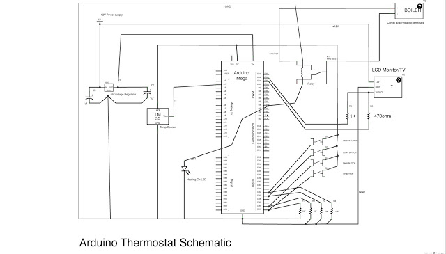
This post outlines the steps taken to build an Arduino-based thermostat, as demonstrated in accompanying videos. The first video showcases a preliminary version of the menu system, providing an overview of the features. The second video presents the completed...
The TLD 5085EJ is a smart LED buck converter featuring an integrated power switch, designed to drive a load current of up to 1.8A with excellent line and load regulation. This device is specifically intended for stepping down input...
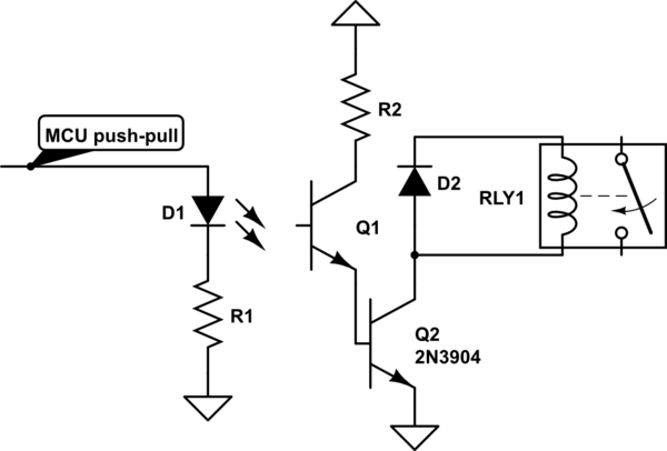
Controlling a relay with an STM32 microcontroller involves using a 4N33 opto-isolator for electrical isolation. The relay coil requires approximately 250 mA, necessitating the use of an MPS222 transistor for switching. The GPIO configuration inverts the logic when used...
Two stepper motors are to be controlled by a dsPIC microcontroller. The programming of the microcontroller has been completed, but there is confusion regarding the use of the L298 driver. Assistance is needed with the circuit design. To control two...