
Arduino Eye Shield

The Arduino Eye Shield circuit provides a robust platform for integrating visual processing capabilities into Arduino projects. The shield's design allows for the interpretation of analog video signals, facilitating the development of applications such as interactive displays and visual feedback systems. The use of the LM1881 for synchronization pulse separation is critical, as it allows the Arduino to focus on specific lines of video data, enhancing the accuracy of the readings.
In terms of the comparator circuit, the AD811 is well-suited for this application, providing fast switching capabilities necessary for real-time video processing. The ability to dynamically set reference levels enables the shield to adapt to varying lighting conditions, thus improving the fidelity of the captured video data. The implementation of multiple sampling points along each line allows for a richer representation of the image, accommodating gray-scale variations that can be crucial for applications requiring nuanced visual feedback.
The integration of an 8x8 LED matrix driven by a MAX7219 expands the versatility of the Eye Shield, enabling the visualization of video data in a compact form factor. The use of the Arduino Matrix library further simplifies the programming and control of the LED matrix, allowing for creative applications such as interactive art installations or responsive displays.
Future enhancements, such as the inclusion of a potentiometer for reference voltage adjustment, will provide users with greater control over the video processing parameters. The ongoing development of a dedicated PCB will also streamline assembly and improve the reliability of the Eye Shield.
Overall, the Arduino Eye Shield represents a significant advancement in the realm of DIY electronics, providing hobbyists and professionals alike with the tools necessary to explore the intersection of video processing and interactive design.The Arduino Eye Shield is a circuit board that can be plugged on top of the Arduino allowing it to interpret analogue video ( PAL or NTSC ) from a camera or other source. It gives the Arduino the power of sight. There are many applications for this. In the example below the video information from the camera is used to drive an 8x8 LED matrix (with a MAX7219 and the Arduino Matrix library ). The PAL and NTSC formats have a relatively straightforward structure. For each line we see a negative-going pulse, then a colour burst, followed by the picture information - where the brightness is determined by the voltage of the signal. Lines follow sequentially to make up a full picture, with additional synchronisation pulses to indicate a new frame.
In the example below we see two lines (and the pulse and sync of the next), where there will be two darker vertical features against a brighter background. For a more complete description see: PAL video timing specification. In the circuit below the LM1881 (IC1) separates the synchronisation pulses from the video signal, allowing the Arduino to identify a specify line of the picture.
To read the information we need to sample the changing voltage along the line, which for PAL takes 52uS. The Arduino`s AnalogRead is too slow (taking about 100uS per sample). The solution used here is to digitise the video signal using a simple comparator circuit, which can then be read by a DigitalRead operation that takes about 4uS, allowing for operations to store the read value, this allows at least 8 samples to be made per line for the picture.
The comparator ( AD811, IC3) sets its output either high or depending on whether the video signal is above or below the reference level. The reference-level is set dynamically by the Arduino. To obtain grey-level information, the same line can be successively sampled with changing reference-levels, or IC4 can also be used to set a second reference level and the two outputs read in parallel.
Using lower-level code Peter Knight suggests tens of samples should be possible per line, using the same hardware. IC2 is a simple unity gain buffer. In the current version, Analog0-Analog3 are set as extra digital inputs to free up the digital pins to drive LEDs etc.
In the next version I will also have the option to set the reference voltages with a potentiometer. I`d like to find a video op-amp in a dual (or more) package and ideally a bit cheaper than the AD811 which has just one in it - suggestions very welcome. The shield is currently built on a protoshield, but I`m working on a PCB design. It is also currently only tested with a PAL signal. The basic code structure is shown below. Here picture data is read in on the even frames and processed on the odd frames. This results in a frame-rate of 25 fps for PAL. int picture[8][8]; void setup() { pinMode(compSyncPin, INPUT); pinMode(vertSyncPin, INPUT); pinMode(burstPin, INPUT); pinMode(oddEvenPin, INPUT); pinMode(videoPin, INPUT); pinMode(refVoltagePin, OUTPUT); setRefVoltage(3.
4f); } void loop(){ int y=0; if(!digitalRead(oddEvenPin){ while(!digitalRead(oddEvenPin); while(!digitalRead(vertSyncPin); while(digitalRead(oddEvenPin){ if(lineCount%38)=0){ for(int x=0;x<8;+x){ picture[x][y]=digitalRead(videoPin); } +y; } +lineCount; while(digitalRead(burstPin); } //this now happens on the odd frame. //process picture data here lineCount=1; } } void setRefVoltage(float v){ if(v>=0 && v<=5. 0){ analogWrite(refVoltagePin, (255*v)/5); } } The Eye Shield was used for my Reflections in Cider installation.
This illuminates a matrix of LEDs inside cider bottles in a window display, to create a video-mirror of the passersby. I`ve got a bunch of things I want to do with the Eye Shield now and I`d love to hear what you think of it too.
Please contribute to this thread on the Arduino forum. Thanks. The wonderful Video Experimenter Shield is based on this design, but makes many signif 🔗 External reference
Related Circuits
The Arduino 2009 functions as an independent weather station without a display. It can operate autonomously for extended periods, sampling data from sensors until the RAM reaches full capacity. The collected data is stored in a designated sector of...
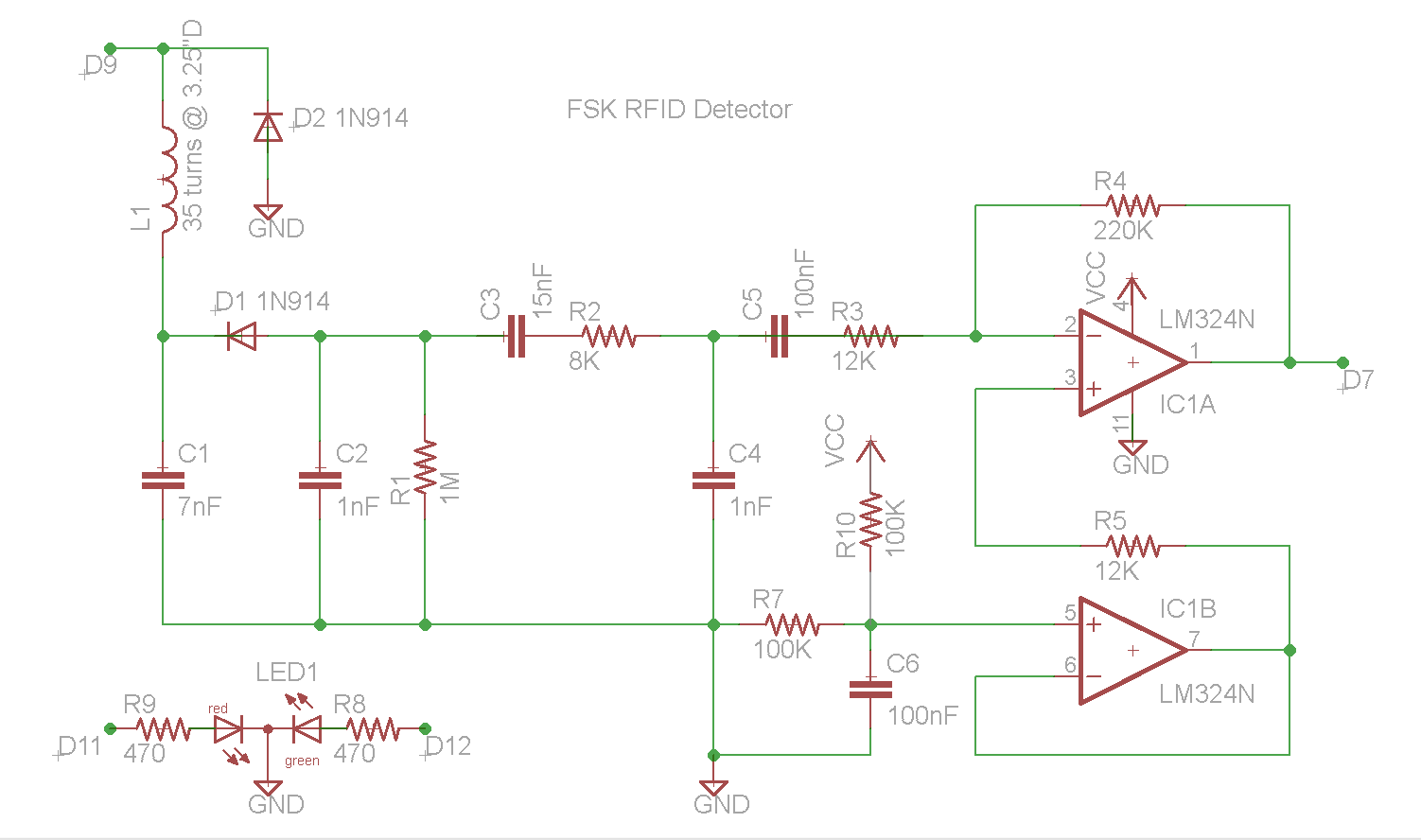
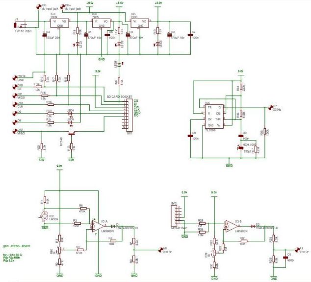
This document describes the construction of an RFID reader utilizing an Arduino (specifically tested with the Nano 3.0, although other models may also be compatible), a hand-wound wire coil, and various low-cost common components. RFID readers are devices manufactured...
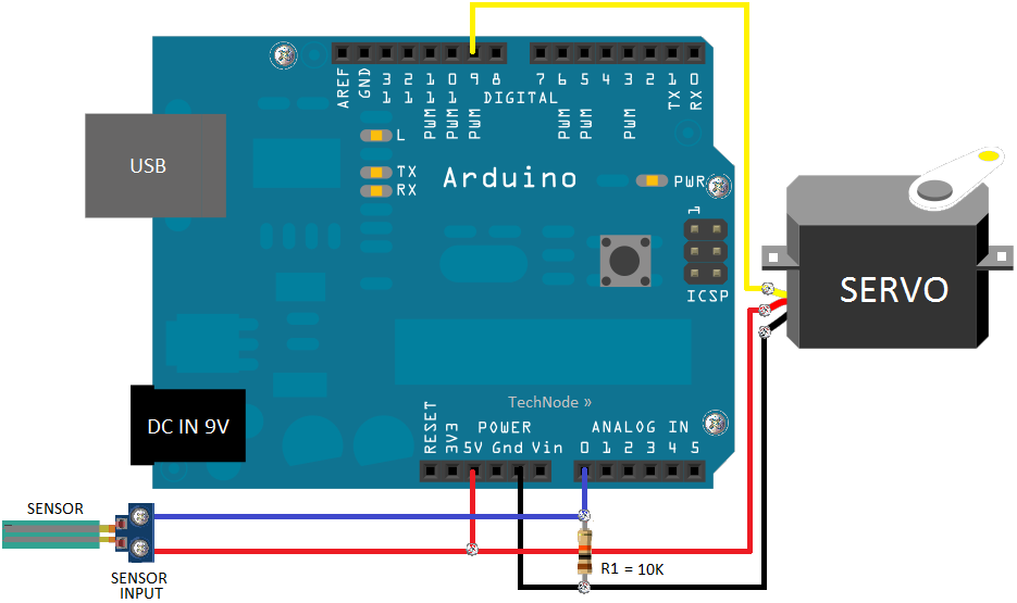
Part fill valves are commonly utilized in rainwater tanks. The valve activates when the water level in the tank drops to a low position. Part fill valves play a crucial role in the management of water levels in rainwater harvesting...
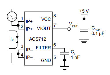
The primary component utilized is the ACS712 sensor from Allegro MicroSystems, designed for measuring current. It offers cost-effective and accurate solutions for AC or DC current sensing in industrial, commercial, and communication systems. A precise, low-offset, linear Hall sensor...
The objective of this post is to consolidate various robot designs and transform them into a new device featuring updated hardware and standardized software, specifically using Arduino, to enhance usability. These robots share three common elements: a mechanical structure,...
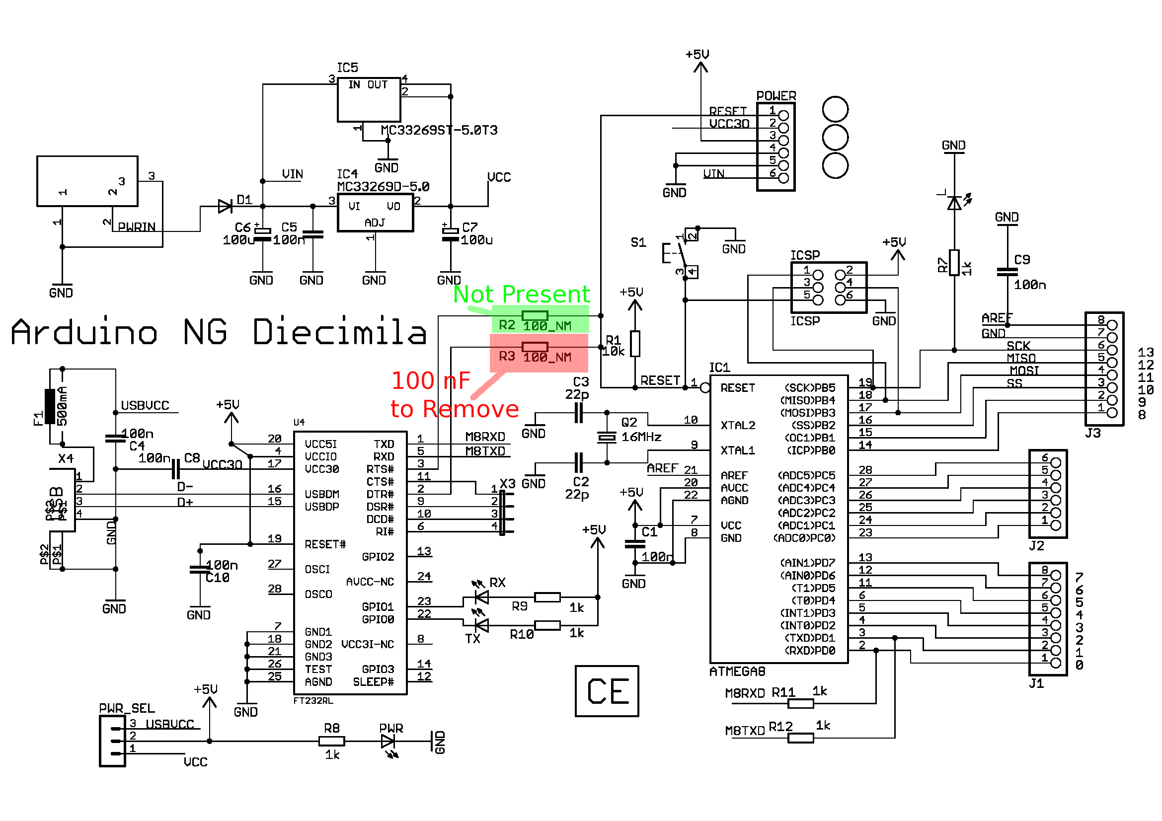
This article discusses the Diecimila; however, there is a newer article that focuses on the Duemilanove. A shift in topic is presented, providing instructions on how to modify an Arduino board to enable useful functions such as debugging. The...