
Robot shield for Arduino

The proposed device aims to integrate several existing robotic designs into a unified platform. This new device will utilize a robust mechanical structure that can accommodate various components and configurations, allowing for flexibility in design and function. The hardware will be based on Arduino, providing a versatile and widely supported environment for development. This choice of microcontroller enables easy programming and modification, catering to users with different levels of expertise.
The software aspect will leverage the Arduino ecosystem, which includes a vast library of pre-existing code and tools that facilitate rapid development. The integration of these elements will not only streamline the building process but also ensure that users can easily customize their robotic devices according to specific requirements. The combination of a well-defined mechanical structure, reliable hardware, and accessible software will provide a comprehensive foundation for creating innovative robotic solutions that are both functional and user-friendly.
By focusing on these core components, the new device aims to simplify the robotics design process, making it more accessible to hobbyists, educators, and professionals alike. The result will be a versatile platform capable of supporting a wide range of robotic applications, from simple educational projects to complex automated systems.The idea behind this post is to bring together some robot designs and trasform them in a new device with new hardware and standard software (arduino of course) and so easier to use. These robots have three things in common: a mechanical structure, the hardware and the software. While the. 🔗 External reference
Related Circuits
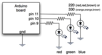
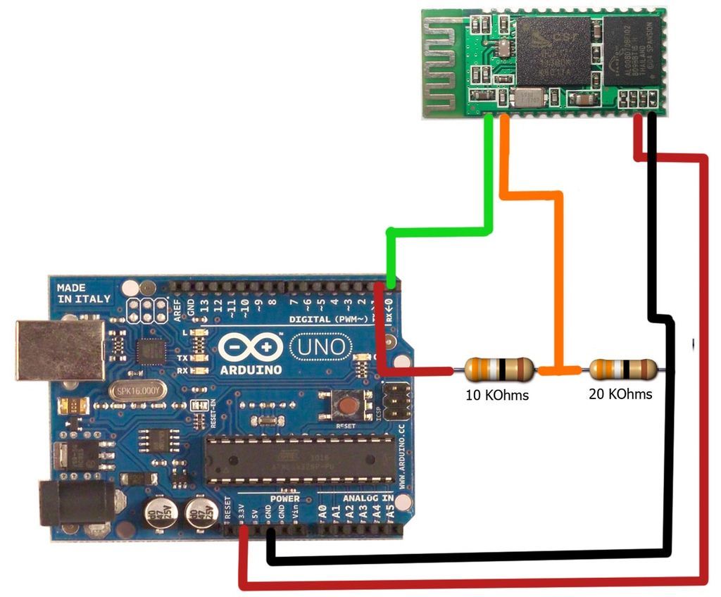
The hardware consists of an Arduino board connected via USB to a laptop, which recognizes the Arduino as a serial device. Three LEDs (red, green, blue) are mounted directly on the Arduino board using a prototyping shield. The schematic...
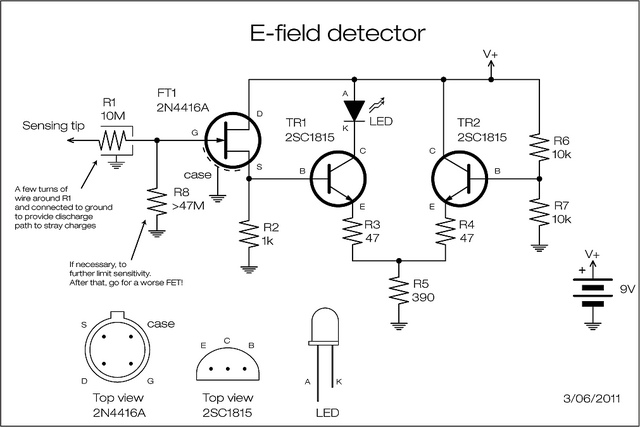
A JFET is employed to detect the electric field generated by high voltage power lines. The JFET amplifies the signal minimally but reduces the impedance and supplies current at a level appropriate for transistor amplification. The two transistors can...
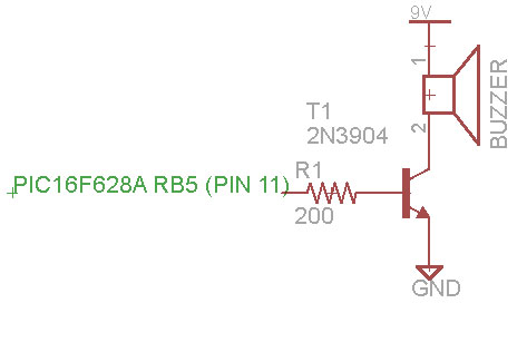
A remote control car can be operated over the internet or wirelessly from a laptop up to 500 meters away. It features a live-feed network camera for driving without line of sight and a horn for signaling. The project...
The motors will be powered by the full source voltage, so it is important to ensure that this does not cause the robot to operate too quickly. The Firebot utilizes GM3 motors powered by a 9V battery; however, in...
The motion games on the Nokia 5800 sparked an interest in creating a real-world version of a racing car controlled by tilting a phone. The motion-controlled robot, named Hercules due to its high torque and speed, is operated via...
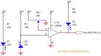
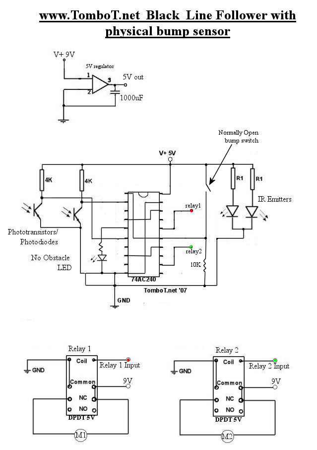
This circuit diagram illustrates a Line Follower / Line Tracker robot. The circuit is derived from tutorial documentation, which is available for download at the conclusion of this article. The line follower robot utilizes eight proximity sensor modules. Each...