
Arduino High Voltage Detector
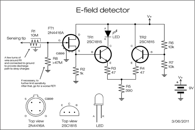
The circuit utilizes a Junction Field Effect Transistor (JFET) as the primary sensing element for detecting electric fields around high voltage lines. The JFET operates by responding to the electric field, which induces a small signal that is then amplified through the subsequent transistor stages. The configuration of the two NPN transistors (Q1 and Q2) is crucial for implementing a threshold detection mechanism. When the voltage across R2 rises above a predetermined threshold, approximately 3V, Q1 activates, allowing current to flow to the LED, which provides a visual indication of the detected field.
The design incorporates a simple yet effective method for enhancing the response of the LED. By utilizing a step curve in the current supplied to the LED, the circuit achieves a clear distinction between the on and off states, improving the user’s ability to interpret the signal. The alternative configuration, which connects a low-current LED directly to the JFET's drain, allows for a continuous linear response but sacrifices the threshold detection feature, which is beneficial in environments with fluctuating electric fields.
To ensure the stability of the JFET operation, the circuit incorporates resistor R1, which serves multiple functions. It not only protects the JFET gate from high voltage spikes but also contributes to the sensing mechanism. The design suggests that a curled tip configuration, along with a high resistance path to ground, helps mitigate the effects of stray charges, which can affect the accuracy of the readings.
The addition of resistor R8, while enhancing safety by providing a discharge path, also introduces a trade-off in sensitivity. The selection of resistor values throughout the circuit is critical, as higher values can improve protection but may also limit the responsiveness of the circuit to low-level electric fields.
Overall, this circuit design exemplifies a practical application of JFET technology in sensing high voltage electric fields, combining elements of analog amplification and threshold detection to achieve reliable performance in potentially hazardous environments.Nothing really new: a JFET is used to sense the electric field generated by high voltage electric line; the JFET amplifies the signal very little, but it lowers the impedence and provide current to a level suitable for transistor amplification. The two transistor can be any low power NPN scavenged from anywhere. The two-transistor are configured a s a sort of thresholded amplifier: when the voltage at R2 rises at above 3V circa, Q1 starts pumping current into the LED with a step curve providing a better go-no/go rensponse. The circuit is the same as the one used in the Korg Monotron to drive the LFO LED. A low current LED could have been connected directly between V+ and the Drain of the JFET and removing TR1, TR2 and R3 through R7: in this case the LED would light up in a linear way, no threshold.
See bottom of post for a description of what TR2 is there for. Stray charge may escape from the tip of R1 for tip-effect letting the intrinsic capacitance at the gate of the JFET charge positively giving a positive read after a little while. So, a curled tip and a very high resistance path to ground in the form of a few turns of thin wire around resistor R1, help keep things in balance.
In case, a very very high resistor can be connected between gate and ground (R8), but this will limit sensitivity very much. Resistor R1 is there to provide a protection to the delicate gate of the JFET and the delicate heart of the operator in case of contact to a live line.
Here, the higher the value of the resistor, the better. R1 also provides for the sensing tip. 🔗 External reference
Related Circuits
This circuit is not a novelty, but it proved so useful, simple and cheap that it is worth building. When the positive (Red) probe is connected to a DC positive voltage and the Black probe to the negative, the...
This is a highly sensitive envelope detector designed for AM radio applications. The circuit, illustrated in Figure 1, enables linear detection of weak signals with a modulation depth of 80-85%. The first stage (VT1) functions as a common-emitter amplifier...
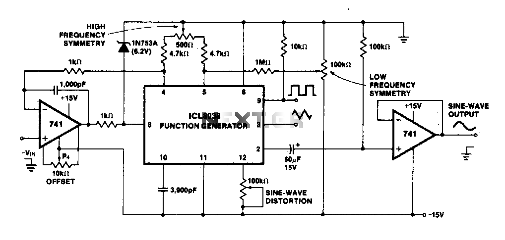
The linearity of the input sweep voltage in relation to the output frequency is significantly enhanced by utilizing an operational amplifier. The utilization of an operational amplifier (op-amp) in electronic circuits is a common practice to improve the linearity of...
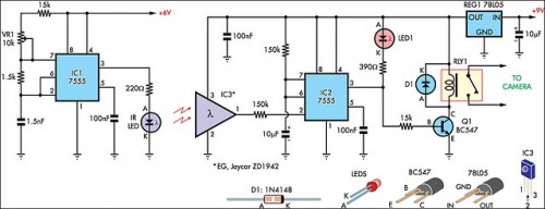
The IR detector (IC3) controls an LM 7555 CMOS timer (IC2) operating in monostable mode. When the beam is interrupted, IC2 is triggered, and its pin 3 output goes high for approximately half a second. This action extinguishes LED1...
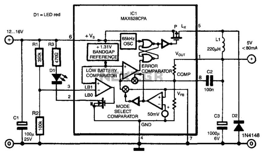
Switch-mode power supplies offer significantly greater efficiency compared to traditional power supplies. The switch-mode regulator described here achieves an efficiency of approximately 85%. It converts an input voltage range of 12 to 16 VDC into a stable output voltage...
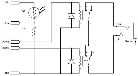
A straightforward project involves using an Arduino to rotate a GH-2 camera on a fluid head by specified degrees to capture 360-degree panoramas. The motor control is uncomplicated, and there is a wealth of DIY motor projects available. Assistance...