
Ultra-simple Voltage Probe
This circuit functions as a simple voltage indicator with dual LED outputs to signify different conditions based on the type of voltage applied. It utilizes two light-emitting diodes (LEDs) – one red and one green – to provide visual feedback regarding the polarity of the voltage being measured and whether it is AC or DC.
The circuit is designed to operate with a DC voltage source. When the positive probe (typically colored red) is connected to the positive terminal of a DC source, the red LED will illuminate. This indicates a proper connection to a positive voltage. Conversely, if the probes are reversed, with the red probe connected to the negative terminal, the green LED will illuminate, indicating reverse polarity.
In the case of an AC voltage source, both LEDs will illuminate simultaneously. This feature allows for quick identification of AC voltage presence, as both LEDs do not light up under DC conditions unless the polarity is reversed.
A crucial component of this circuit is the inclusion of a current-limiting bulb that ensures the LEDs do not exceed their maximum current rating of 40mA, particularly when connected to high AC voltages, such as 220V. The bulb serves two purposes: it limits the current flowing through the LEDs and provides a visual indication of voltage presence. The filament of the bulb begins to glow at approximately 30V AC, becoming brighter as the voltage increases. This characteristic can be useful for applications requiring a visual confirmation of voltage levels.
The circuit's simplicity and low cost make it an attractive option for electrical testing and educational purposes, allowing users to easily identify voltage types and conditions without the need for complex instrumentation.This circuit is not a novelty, but it proved so useful, simple and cheap that it is worth building. When the positive (Red) probe is connected to a DC positive voltage and the Black probe to the negative, the Red LED will illuminate. Reversing polarities the Green LED will illuminate. Connecting the probes to an AC source both LEDs will go on. The bulb limits the LEDs current to 40mA @ 220V AC and its filament starts illuminating from about 30V, shining more brightly as voltage increases.
🔗 External reference
Related Circuits

A potentiometer (RP) is utilized for adjusting the operating voltage of the relay (KA) to ensure that the motor operates normally, especially when the relay (KA) does not function reliably during the action phase. The circuit involves a potentiometer...

When testing a circuit, a variable voltage source with overvoltage shutdown capabilities is highly beneficial. In this circuit, resistor R1 is adjusted to a value 1 to 2 volts below the eventual shutdown threshold. Resistor R2 is responsible for...
The output of the transformer has been calculated to be 125 times higher than the input, based on the ratio of 1000 to 8. Given an input of 12V, the expected output should be 1500V, although there is some...

The circuit depicted is designed to protect a system from power supplies that may exceed safe limits. An example of this is small consumer products that utilize external AC adapters, where there is a risk of accidentally connecting the...
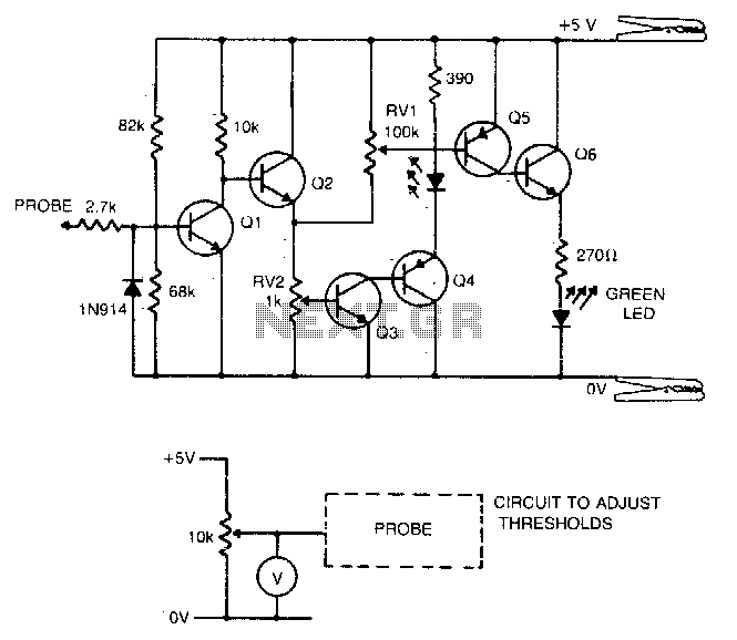
Transistors Q1 and Q2 create a buffer that offers the probe a suitable input impedance. Q3 and Q4 constitute a level detection circuit. When the voltage across the base-emitter junction of Q3 exceeds 0.6 V, the transistor activates, which...
All miniature electronic devices operate off batteries. Some of them require higher than the standard battery voltages for efficient operation. If a battery with the specific voltage is unavailable, additional cells must be connected in series to increase the...
Warning: include(partials/cookie-banner.php): Failed to open stream: Permission denied in /var/www/html/nextgr/view-circuit.php on line 713
Warning: include(): Failed opening 'partials/cookie-banner.php' for inclusion (include_path='.:/usr/share/php') in /var/www/html/nextgr/view-circuit.php on line 713