
Sensitive envelope detector circuit diagram
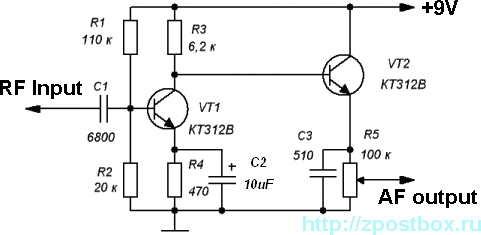
The envelope detector circuit described employs two transistors to achieve effective AM signal demodulation. The first stage, VT1, is configured as a common-emitter amplifier, which amplifies the incoming AM signal. This stage is critical for enhancing weak signals, allowing for better detection of the envelope of the modulated waveform. The common-emitter configuration is known for providing significant voltage gain, which is essential when dealing with low-level AM signals.
Following the amplification stage, the second transistor, VT2, is configured as an emitter-follower. This configuration is characterized by its high input impedance and low output impedance, which effectively isolates the first stage from the load. The low current operation of VT2, facilitated by the high resistance of resistor R5, is crucial in minimizing power consumption while maintaining performance. This low current operation also helps to reduce thermal noise, further enhancing the sensitivity of the envelope detector.
The demodulation process occurs at the lower bend of the volt-ampere curve, a region that allows for optimal linearity in signal processing. The deep negative feedback employed in the emitter-follower stage significantly contributes to the high linearity of the demodulated output. This feedback mechanism helps to stabilize the gain and improve the overall fidelity of the detected audio signal.
In summary, this envelope detector circuit leverages the strengths of both common-emitter and emitter-follower configurations to achieve precise AM signal demodulation, making it suitable for applications requiring high sensitivity and linear detection of modulated signals.This is a very sensitive envelope detector for AM radio. The circuit (see Fig. 1) provides linear detection of weak signals with modulation depth of 80. 85% The first stage (VT1) is a common-emitter amplifier circuit for input signals, the second stage is an emitter-follower circuit (VT2). The transistor VT2 operates at low current because of the hi gh resistance of the resistor R5. The process of AM demodulation occurs at the lower bend of the volt-ampere curve. A high linearity of demodulation provided by the deep negative feedback in the emitter-follower circuit. 🔗 External reference
Related Circuits
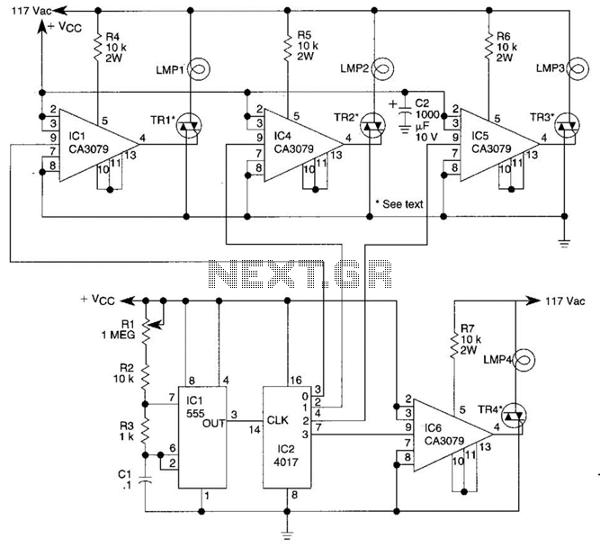
A 555 timer (IC1) controls a 4017 CMOS decade counter. The first four outputs of the 4017 drive a CA3079 zero-voltage switch. Pin 9 of the CA3079 is utilized to inhibit output from pin 4, effectively disabling the stream...
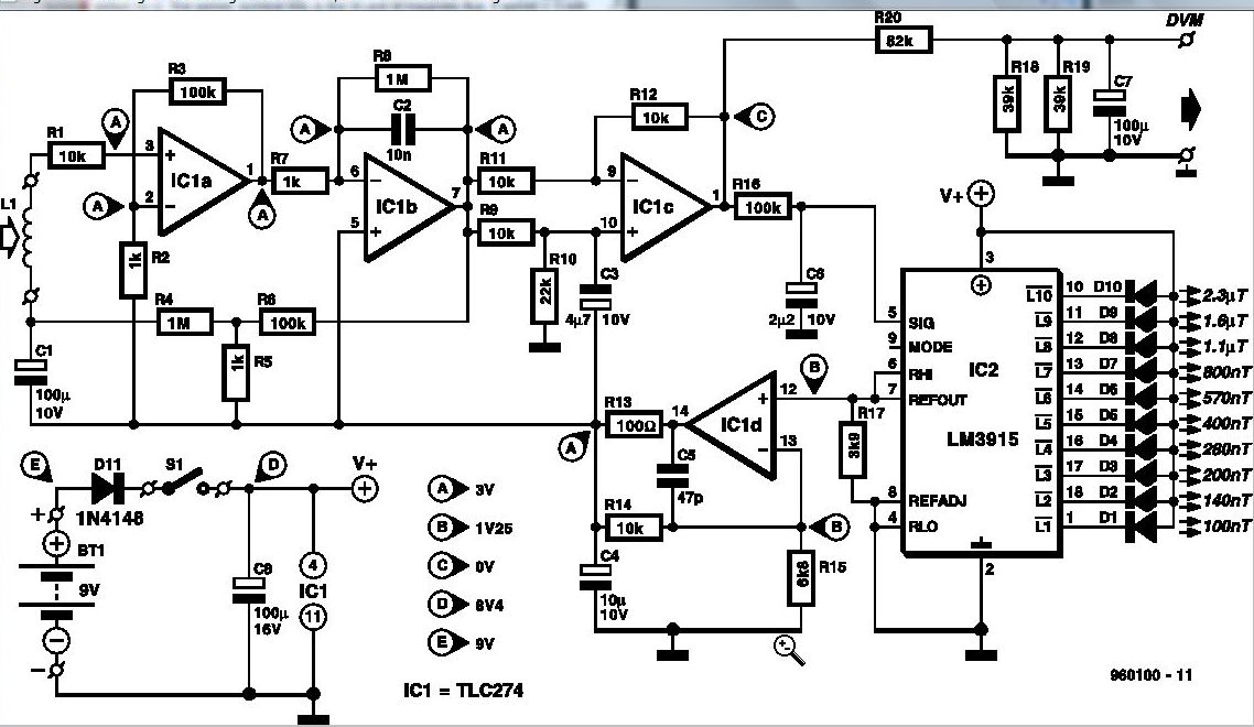
Some experts believe that static magnetic fields (SMFs) may affect the physical well-being of individuals. If one subscribes to this viewpoint, the magnetic-field meter described here will aid in locating sources of SMFs and assessing their strength. These results...

It is embarrassing to acknowledge that the blog post from April 29 contained several schematic errors of my own making, particularly in the variation of Morgan Jones's circuit. One of the resistor values was incorrect by a factor of...
Common mode input voltage up to a difference of 100V enlarged circuit diagram. The circuit diagram described features a design capable of handling a common mode input voltage with a differential range of up to 100V. Such a configuration is...
The clock is based on the PIC16F877 microcontroller from Microchip Technology Inc., which performs all of the logic necessary to decode the MSF signal and display the time on twelve 7-segment displays. The circuit design incorporates the PIC16F877 microcontroller, a...
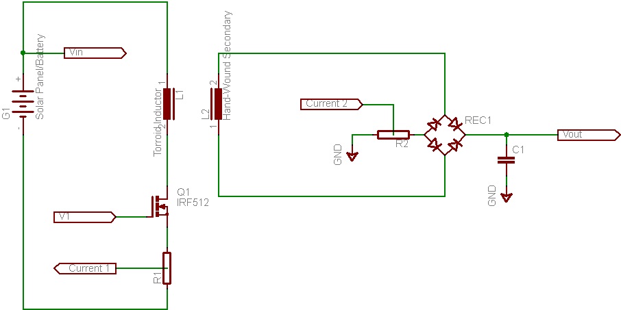
This document discusses the future direction of the Free Charge Controller project and proposes a new solar charge controller circuit. The Free Charge Controller project aims to enhance the efficiency and effectiveness of solar energy management systems. The proposed solar...