
arduino LCD thermometer
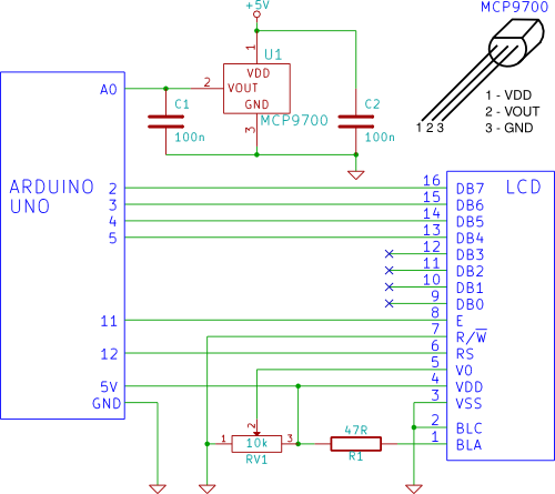
The circuit involves an MCP9700 temperature sensor, which is a linear active thermistor IC capable of providing a voltage output that corresponds to the temperature. The output voltage from the MCP9700 is proportional to the temperature, typically with a scale factor of 20 mV/°C. This output is connected to the analog input pin A0 of the Arduino, which is responsible for reading the sensor's voltage.
The Arduino processes the analog voltage signal received from the MCP9700. Using the analog-to-digital converter (ADC) built into the microcontroller, the Arduino converts the analog voltage into a digital value that represents the temperature. The formula to convert the ADC value back to temperature in Celsius is:
\[ \text{Temperature (°C)} = \left( \frac{\text{ADC Value} \times \text{V}_{\text{ref}}}{1023} - 0.5 \right) \times 100 \]
where \( \text{V}_{\text{ref}} \) is the reference voltage of the Arduino, typically 5V.
The LCD is interfaced with the Arduino to display the temperature readings. A common choice for this application is a 16x2 character LCD, which requires a few additional components, such as a potentiometer for contrast adjustment and appropriate connections to the Arduino. The LCD operates using a specific library that simplifies communication with the Arduino, allowing for easy display of the temperature readings.
The connections between the MCP9700, Arduino, and LCD must be correctly established for the circuit to function properly. The MCP9700's VCC pin is connected to the Arduino's 5V output, the GND pin to the Arduino's ground, and the output pin to analog pin A0. The LCD is connected according to its specifications, typically using digital pins for data and control signals.
This setup demonstrates a basic yet effective way to monitor and display temperature using an Arduino platform, combining the simplicity of the MCP9700 sensor and the versatility of an LCD for visual output.A temperature sensor (MCP9700 linear active thermistor IC) and LCD are connected to the Arduino in this tutorial. The Arduino reads the temperature from the MCP9700 on analog pin A0 and displays the temperature on the LCD..
🔗 External reference
Related Circuits
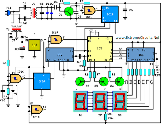
This circuit is designed for precise measurement of temperature in degrees Celsius. It features a transmitter section that converts the output voltage from a temperature sensor, which is proportional to the temperature being measured, into frequency. The resulting frequency...
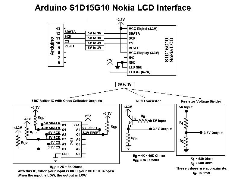
This is the first color graphic LCD display encountered. Initial assumptions were made regarding the connections, specifically that the Chip Select (CS) and RESET pins could be tied high for simplicity, based on previous experience with TTL logic. However,...

A unified thermometric controller that can be programmed with simple scripts, integrating the "classic" thermometer/controller pair. You can build a variety of simple machines with the same hardware and a different script: a charting thermometer, a vending machine that...
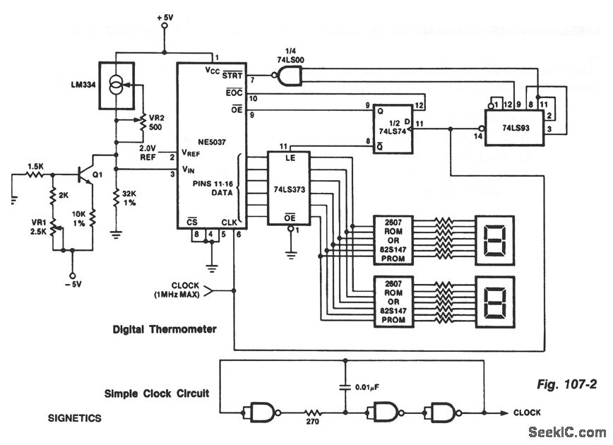
The ROMs or PROMs must contain the correct code for converting data from the NE5037, which serves as the address for the ROMs or PROMs, into the appropriate segment driver codes. The displayed temperature can be converted to degrees...
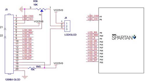
The Spartan-6 board features a 2x16 LCD, as illustrated in the accompanying figure. This 2x16 character LCD interface card supports both 4-bit and 8-bit modes, and it includes a facility for contrast adjustment via a trim potentiometer. In the...
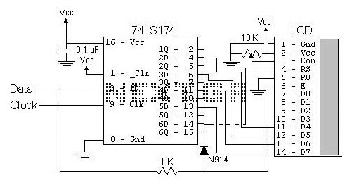
The most popular LCD interface is the Hitachi 44780 based LCD controller chip which provides a fairly easy to work with interface and low power consumption. The major drawback of the interface is the perceived complexity of working with...