
Digital Remote Thermometer
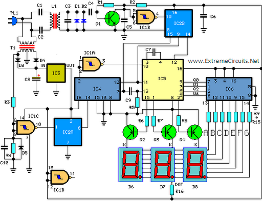
The circuit employs IC1 as a precision temperature sensor, providing a linear output of 10 mV/°C, which drives IC2, a voltage-to-frequency converter. At its output pin (3), an input of 10 mV is converted into 100 Hz frequency pulses. For instance, a temperature of 20 °C results in IC1 producing 200 mV, which IC2 converts to 2 kHz. Q1 serves as the driver for the power output transistor Q2, which is connected to the mains supply through components L1, C7, and C8. The frequency pulses received from the mains supply are safely insulated by capacitors C1, C2, and inductor L1, and are then amplified by Q1. Diodes D1 and D2 limit peak voltages at the input. The pulses are filtered by capacitor C5, squared by IC1B, and divided by 10 using IC2B before being sent to the clock input of IC5 for counting.
IC4 functions as the time-base generator, supplying reset pulses for both IC1B and IC5, while also enabling latches and gate-time for IC5 at a frequency of 1 Hz. This time-base generator is driven by a 5 Hz square wave derived from the 50 Hz mains frequency, which is picked up from the secondary side of transformer T1, squared by IC1C, and divided by 10 in IC2A. IC5 controls the cathodes of the displays through transistors Q2, Q3, and Q4 at a multiplexing rate determined by capacitor C7. It also drives the parallel anodes of the three displays via a BCD-to-7 segment decoder, IC6. In summary, input pulses from the mains supply, such as a 2 kHz frequency, are divided by 10 and displayed as 20.0 °C on the LED displays.This circuit is intended for precision centigrade temperature measurement, with a transmitter section converting to frequency the sensor`s output voltage, which is proportional to the measured temperature. The output frequency bursts are conveyed into the mains supply cables. The receiver section counts the bursts coming from mains supply and show s the counting on three 7-segment LED displays. The least significant digit displays tenths of degree and then a 00. 0 to 99. 9 °C range is obtained. Transmitter-receiver distance can reach hundred meters, provided both units are connected to the mains supply within the control of the same light-meter. IC1 is a precision centigrade temperature sensor with a linear output of 10mV/ °C driving IC2, a voltage-frequency converter.
At its output pin (3), an input of 10mV is converted to 100Hz frequency pulses. Thus, for example, a temperature of 20 °C is converted by IC1 to 200mV and then by IC2 to 2KHz. Q1 is the driver of the power output transistor Q2, coupled to the mains supply by L1 and C7, C8. The frequency pulses coming from mains supply and safely insulated by C1, C2 & L1 are amplified by Q1; diodes D1 and D2 limiting peaks at its input. Pulses are filtered by C5, squared by IC1B, divided by 10 in IC2B and sent for the final count to the clock input of IC5.
IC4 is the time-base generator: it provides reset pulses for IC1B and IC5 and enables latches and gate-time of IC5 at 1Hz frequency. It is driven by a 5Hz square wave obtained from 50Hz mains frequency picked-up from T1 secondary, squared by IC1C and divided by 10 in IC2A.
IC5 drives the displays` cathodes via Q2, Q3 & Q4 at a multiplexing rate frequency fixed by C7. It drives also the 3 displays` paralleled anodes via the BCD-to-7 segment decoder IC6. Summing up, input pulses from mains supply at, say, 2KHz frequency, are divided by 10 and displayed as 20. 0 °C. 🔗 External reference
Related Circuits
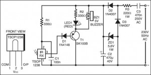
The following circuit illustrates an IR Remote Control Tester Circuit. Features include that transistor T1 conducts during the negative pulse period, and there is a data output pin. The IR Remote Control Tester Circuit is designed to verify the functionality...
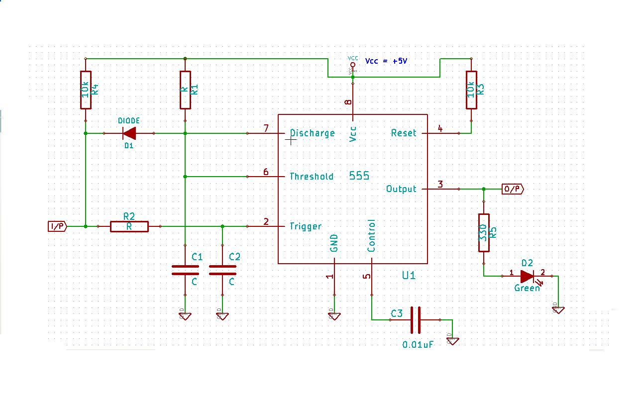
Create a 555 timer-based circuit where the output pin of the 555 timer is held low by default when powered on, and the input pin is held high at power on. The main requirement is that the output pin...
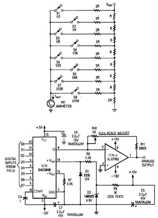
Figure A illustrates an R/2R resistor ladder. Each closed switch increases the current output. A basic channel A/D converter is depicted in Figure B. The voltage reference (D2) is shared among all channels, while the value of the dropping...
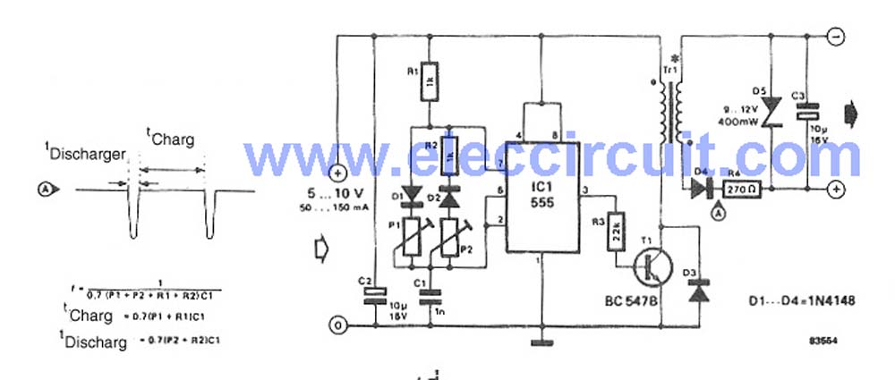
This circuit is a simple DC to DC converter designed for digital circuits. It operates with a supply voltage of 5V and provides an output voltage that steps up to a maximum of 10V-12V DC. The circuit utilizes an...
This remote controller can be fitted to any preamplifier for distance volume control. Basically, it is a motor controller circuit with IR that turns the potentiometer left or right. The remote controller circuit described functions as an interface for adjusting...
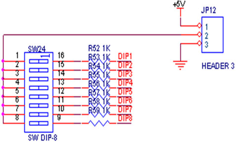
A switch is an electrical component that can break an electrical circuit, interrupting the current or diverting it from one conductor to another. A switch may be directly manipulated by a human as a control signal to a system...