
arduino controllers and sensors
The Arduino microcontroller is a versatile platform widely used in robotics and automation projects. It provides a simple interface for controlling various electronic components. The ability to output 40mA at 5V makes it ideal for driving low-power devices such as LEDs. However, many applications require more power, necessitating the use of additional components to interface with higher current devices like motors and solenoids.
To facilitate this, an H-bridge circuit can be constructed using transistors salvaged from discarded electronic devices, such as ATX power supplies. An H-bridge allows for bidirectional control of motors, enabling them to spin in both clockwise and counterclockwise directions. The circuit typically consists of four transistors arranged in a bridge configuration, with control inputs that determine the direction of the motor's rotation.
In applications involving stepper motors, the circuit can be adapted to control the stepping sequence. Stepper motors are advantageous in applications requiring precise positioning, such as in 3D printers and CNC machines. By supplying pulses to the motor's inputs in the correct sequence, it is possible to achieve controlled movement. The torque characteristics of stepper motors can be enhanced by increasing the supply voltage, allowing for more robust performance in demanding applications.
Furthermore, the inclusion of protection diodes in the circuit is critical when dealing with inductive loads. These diodes prevent back EMF generated by the inductive components from damaging the transistors, ensuring the longevity and reliability of the circuit. For non-inductive loads, such as LEDs, the protection diode can be omitted, simplifying the circuit design.
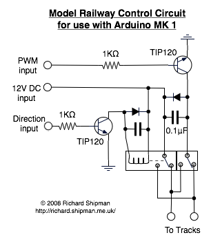
Overall, the integration of salvaged components and the Arduino microcontroller provides a cost-effective and efficient approach to building electronic circuits capable of controlling a wide range of devices. This methodology not only promotes sustainability through the reuse of electronic waste but also fosters innovation in the development of robotic and automated systems.The Arduino microcontroller board is able to supply a current of 40mA from its output connections. These digital outputs are fixed at 5V ON or 0V OFF . This is adequate for working with LEDs but devices such as motors, solenoids, high brightness LEDs etc. may require much higher currents and voltages. To achieve this an interface in between t he Arduino and the device can be made from locally sourced components. Suitable transistors can be found in a wide variety of waste electronic items. Internet resources are available to check part numbers for a components specification and, interestingly, retail price. In the following example all the components were found in a discarded ATX computer power supply. The circuit can also be used with other inductive loads, such as solenoids and relays. For other, non-inductive, loads (LEDs etc. ) the protection diode D1 can be omitted. In this example the ATX components used were: This circuit has been initially tested with 12V motors drawing 500mA without a heatsink.
This is more than adequate for initial experiments in the FabLab, though it may be worth noting that the transistor is rated at 400V and 3A. The H-bridge circuit enables a motor to be spun in either direction and stopped from two control inputs.
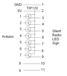
A steerable robot can be made using this circuit, together with a second circuit and DC motor. This circuit was made using components taken from various discarded sources and previous projects. The LEDs were added to aid debugging and comparing the performance of different DC motors. The transistors used are relatively low current devices but have been tested driving motors sourced from printers up to 250mA. A second, more powerful, circuit will be built when a suitable source of pnp transistors is found to complement the npn transistors sourced from a ATX computer power supply.
Using the circuit from the first example a simple circuit can be made for controlling unipolar (5 wire) stepper motors. Such motors can be found in printers, scanners, fax machines etc. along with components to build the circuit. Further information on identifying, connecting and driving can be found on the Stepper Motors page. Once the motor`s wiring sequence has been determined it can be connected to the circuit. The motor is made to rotate by alternately supplying pulses to each input. Reversing the sequence of pulses reverses the direction of rotation. Stepper motors have relatively low torque (which may be increased with voltage) but have the advantage of low current and precise positioning.
🔗 External reference
Related Circuits
How to connect and program the Arduino/Atmega168 microcontroller to operate a unipolar stepper motor. To connect and program the Arduino/Atmega168 microcontroller for operating a unipolar stepper motor, the following steps should be followed: 1. **Components Required**: - Arduino or...
The project addresses a brightness issue with the LED display. The original design using a 4017 counter was ineffective because it lacked the capability to turn off the display while updating the shift registers. Consequently, the decision was made...
When starting with Arduino, one often accumulates more Arduino boards than RS232 or USB ports available on the computer. Therefore, it is more practical to use an external signal level converter rather than placing it directly on the Arduino...
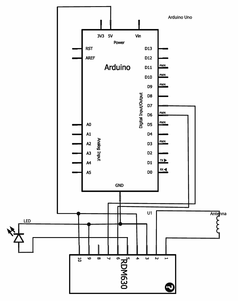
This tutorial provides guidance on integrating RFID functionality into a project using the RDM630 module from Seeed Studio, specifically its UART version. The module is mounted on a compact board with pre-soldered connectors, making it compatible with breadboards. To...
This integrated circuit is highly efficient and does not require any external glue logic for operation. It features two pins to control a motor: one for direction and the other for stepping pulse triggers. The design is compact and...
A model railway operates under computer control, utilizing a laptop to send commands via the USB port to an Arduino. The Arduino employs PWM (Pulse Width Modulation) to regulate the speed of the train. There were several challenges encountered,...