
arduino uno schematic

The Arduino Uno microcontroller board, based on the ATmega328, serves as a versatile platform for a wide range of electronic projects. The board's 14 digital I/O pins allow for extensive interfacing with various components, while the 6 analog inputs facilitate the connection of sensors and other analog devices. The inclusion of a 16 MHz crystal oscillator ensures stable operation and timing accuracy, which is critical for real-time applications. The USB connection allows for easy programming and communication with a computer, while the power jack provides an alternative power supply option, enhancing the board's flexibility in different environments.
The 800-watt audio amplifier schematic showcases a robust design utilizing MOSFETs, which are known for their efficiency and ability to handle high power levels. This amplifier is designed to deliver exceptional sound quality with low distortion, making it ideal for applications such as sub-woofer amplification or high-powered surround sound systems. The schematic likely includes key components such as the input stage, output stage, power supply circuitry, and feedback mechanisms to optimize performance.
The A/B Box pedal schematic, designed by Rick Barker, represents a practical solution for musicians needing to switch between different audio sources. The low-noise dual preamp enhances the signal integrity, ensuring that the sound quality remains high when switching between microphones or instruments. This pedal design is particularly beneficial for harmonica players but can be adapted for various applications in electric guitar setups. The schematic may include details on the input/output jacks, switching mechanism, and power supply requirements, providing a comprehensive guide for construction and use.
Overall, these schematics represent significant contributions to the fields of microcontroller applications and audio amplification, showcasing the versatility and capability of modern electronic design.Here the Arduino UNO schematic diagram (click to enlarge): About Arduino UNO: The Arduino Uno is really a microcontroller board based on the ATmega328. It has 14 digital input/output pins (of which 6 may be employed as PWM outputs), 6 analog inputs, a 16 MHz crystal oscillator, a USB connection, a power jack, an ICSP.
Here the schematic diagram o f 800 watt audio amplifier with MOSFET. This amplifier can be used for practically any application that requires high power, low noise, distortion and excellent sound. Examples would be Sub-woofer amp, FOH stage amplifier, One channel of a very high-powered surround sound amplifier etc.
For detail explanation about how this circuit. This is a A/B Box pedal schematic for electric guitar was designed by Rick Barker. This A/B Box effect was originally designed for switching between different harmonica mics. This A/B Box featured low noise dual preamp for better effect. Download the schematic of A/B Box Guitar Effect: Download Link 🔗 External reference
Related Circuits
How to connect and program the Arduino/Atmega168 microcontroller to operate a unipolar stepper motor. To connect and program the Arduino/Atmega168 microcontroller for operating a unipolar stepper motor, the following steps should be followed: 1. **Components Required**: - Arduino or...
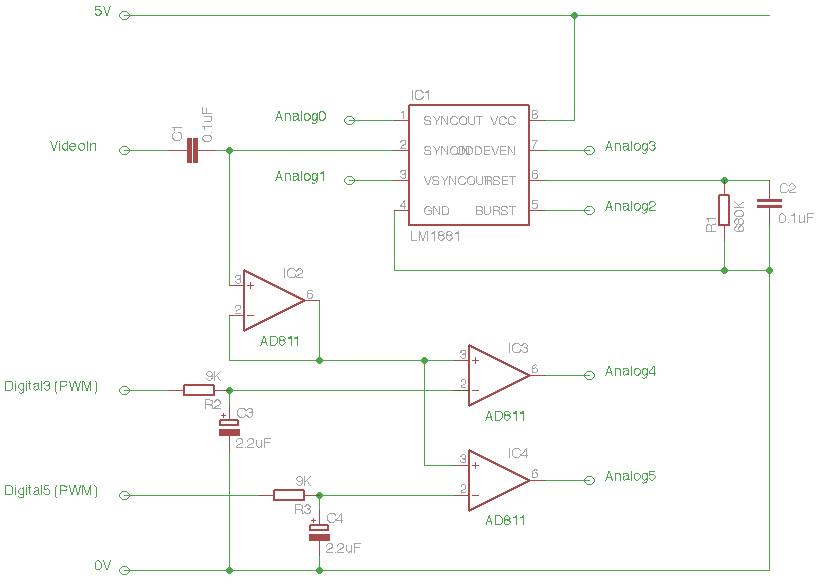
The Arduino Eye Shield is a circuit board that can be plugged on top of the Arduino, enabling it to interpret analog video (PAL or NTSC) from a camera or other source. This provides the Arduino with visual capabilities,...
Almost all 24V power systems in trucks, 4WDs, RVs, boats, etc., utilize two series-connected 12V lead-acid batteries. The charging system can only sustain the total voltage of the individual batteries. If one battery is failing, this circuit will illuminate...
This is a diagram of a car audio active loudspeaker utilizing the LF353 operational amplifier from National Semiconductor. For optimal performance, the NE5532 is recommended to split the audio signal into three frequency bands using an active filter. The...

The schematic for an infrared burglar alarm circuit is depicted in Figure 1. The infrared transmitter operates as a multivibrator with an oscillation frequency of 40 kHz, utilizing the NE555 integrated circuit (IC2), along with resistors R1 and R2...
After experimenting with a stereo version of the VU meter described in a previous blog post, a studio-grade VU meter is now being presented. This meter features 24 steps, spaced equally every 3 dB, and covers a wide dynamic...