
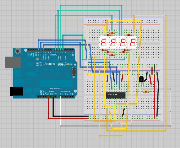
Arduino Multiplexing
The circuit design for the Nixie tube display system incorporates a series of components working in tandem to achieve effective numeral representation. The IN-12A tubes, with their unique cathode configurations, are driven by a high-voltage decoder that efficiently translates binary input from a microcontroller, such as an Arduino. The 74141 decoder is essential for selecting which of the ten cathodes to activate based on the four-bit binary input, ensuring that only one numeral is displayed at a time to prevent overloading the circuit.
An anode driver circuit, utilizing transistors like the MPSA42 and MPSA92, is critical for managing the high voltage required by the Nixie tubes. The MPSA42 acts as an amplifier for the microcontroller's output, allowing for sufficient current to flow through the MPSA92, which is responsible for supplying the high voltage to the tube. This arrangement ensures that the delicate balance between voltage and current is maintained, allowing for reliable operation of the Nixie tubes without exceeding the power ratings of the components involved.
The multiplexing technique employed allows for rapid switching between tubes, creating the illusion of all tubes being lit simultaneously. This is achieved by carefully timing the activation of each tube, ensuring that the persistence of the Nixie tube's glow compensates for the brief periods of darkness. The software implementation must account for the delay required for each tube to stabilize before switching, optimizing the display for clarity and visibility.
Overall, this circuit design exemplifies a sophisticated approach to utilizing vintage Nixie tubes in modern applications, merging classic technology with contemporary microcontroller capabilities to create an engaging and visually appealing display.The Nixies I`m using have 10 cathodes (shaped like numerals) and a screen-like anode. These are old Russian IN-12A`s that I obtained from an excellent Ukrainian shop on eBay. Other Nixies might have more cathodes for a decimal point or other symbols (like the IN-12B shown below). Since it`s not important to show which pins connect to which cathodes for the following diagrams, I`m going to show
all the cathodes as one and just notate that there is a 10-line bus going into the tube. Similarly, the 74141 or Russian equivalent decoder chip, which translates a four-bit nibble into one of ten output pins, will be shown as a simple rectangle with a four-line bus going in and a ten line bus coming out. So, let`s dive into the schematic. (you can see a small copy here or at Now, as an alert reader pointed out, there`s a typo on the ArduniNIX schematic in the anode drivers the MPSA42 is shown with a PNP symbol instead of the NPN device that it is.
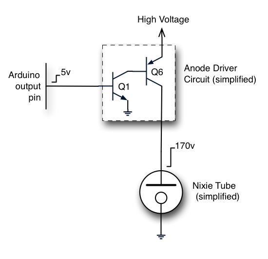
But don`t worry the circuit actually works the right way. Here`s a simplified diagram of one anode driver circuit that shows the transistors but omits the biasing and current-limiting resistors. When your software turns on the output pin to enable the anode, the MPSA42 at Q1 amplifies the microcontroller`s wimpy little output current and turns on the MPSA92 at Q6.
These are high-voltage transistors and they are able to supply current to the Nixie tube at the high voltage it requires. It doesn`t need much current, only a few milliamps, so they don`t need to handle a lot of power. It`s the breakdown voltage that`s the important parameter. Now, I`ve shown the cathode side of the tube as going straight to ground. In reality, the circuit uses a 74141 high voltage decoder (or Russian K155N equivalent). This circuit converts four bits, presented simultaneously by four Arduino output pins, into one of ten output pins one at a time.
It implements a table that looks something like this: So, let`s put the anode driver circuit (represented now as just a box) and the cathode driver decoder chip together and see how the ArduiNIX connects to four tubes. You should only drive one tube at a time, for two reasons: 1) you don`t want to make the decoder pull too much current and exceed it`s maximum dissipation rating and 2) it`s boring to have all the tubes show the same numeral at the same time!
The software switches from one tube to another quickly in a process called multiplexing. If you light up each tube faster than 20 or 30 times a second, they all appear to be on at the same time. You have to pause on each tube and keep it lit for a millisecond or so. Nixies are slower than semiconductors. It can take from 10 mS up to 50 mS to get all those glowing ions moving from a cold start. Even after the tube is up and running, it can take at least a millisecond to light up the second cathode when you are switching from one cathode to another.
So, your code needs to set the decoder, turn on the appropriate anode driver to light up the tube, and leave it that way for a relatively long time. Your code can go off and do other stuff while the tube stays lit, however, so there`s no worries. On the positive side, Nixies stay lit for a similarly long time period (10 mS or more) after you remove the voltage, so this persistence works to our advantage during multiplexing.
// Variables // first, keep the numerals in an array byte NumberArray[8]={0, 0, 0, 0, 0, 0, 0, 0}; const byte numberOfPairs = sizeof(NumberArray)/2; // Set the minimum time to keep a tube lit const byte MinimumNixieDelay=5; // Remember when we can light up the next tube pair. // This needs to be big to reduce rollover problems unsigned long TimeForNextNixie; // Keep track of which pair of tubes are lit int tubePair; //
🔗 External reference
Related Circuits
Control a small DC motor using an H-bridge with an Arduino Uno. The objective is to enable the motor to rotate in different directions based on left and right key presses on a keyboard. The provided code includes the...
The Circuit is composed of two sections, the light sensing and the power switching. The light sensing part consists of a photo-resistor R4, connected like a voltage divider to R2. Since the resistance of the photo-resistor changes depending on...

To power the device, a clean and stable source of 5 volts DC is required. This can be achieved by using a switching 5V DC power supply from a supplier such as JK Electronics, ordering one from Jameco, or...
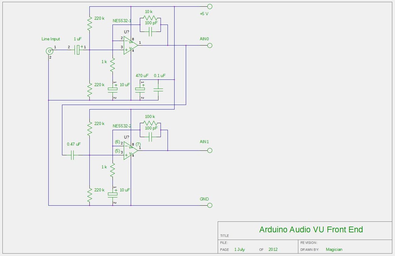
After experimenting with a stereo version of the VU meter described in a previous blog post, a studio-grade VU meter is now being presented. This meter features 24 steps, spaced equally every 3 dB, and covers a wide dynamic...
The intention is to utilize this code in future projects involving 7-segment displays. For those interested in learning more about 7-segment displays, additional information can be found in a related post. 7-segment displays are widely used in electronic devices for...
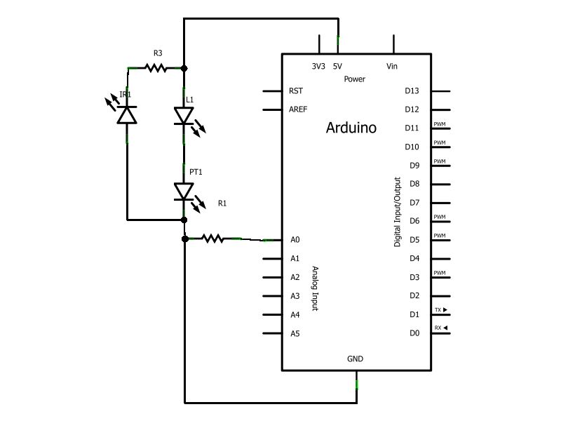
Have you ever wanted to create a line-following robot but found infrared sensors too expensive? If you are located in the UK and have access to a Maplin store nearby, you can purchase infrared transmitters and receivers for just...