
art364 / Standalone Arduino

To implement the 5V power supply, the 7805 voltage regulator is a popular choice due to its reliability and ease of use. The input voltage must be higher than 5V, typically in the range of 7V to 12V, to ensure proper regulation. The regulator requires two decoupling capacitors—one on the input side (typically 0.33µF) and one on the output side (typically 0.1µF)—to filter out any noise and stabilize the voltage output.
For the assembly, a breadboard allows for easy prototyping and modification of the circuit, enabling quick adjustments and testing. However, for a more robust and permanent setup, the copper-clad perf board is recommended. This board facilitates soldering of components directly onto the copper pads, which provide a solid electrical connection. The layout should be carefully planned to minimize the length of connections and reduce potential interference.
When selecting an enclosure, the choice of material should consider factors such as durability, insulation, and ease of access for future modifications. Proper ventilation may also be necessary if the circuit generates heat during operation. Overall, attention to detail in both the power supply design and the assembly of components within the enclosure will contribute to the overall performance and reliability of the electronic device.To power it up you need a clean stable source of 5 volts DC. This means that you either pick up a switching 5v DC power supply from our favorite JK Electronics, mail order one from Jameco or you will have to wire up a voltage regulator. Page 254 of Phys Comp has a nice layout of a 7805 voltage regulator with a couple decoupling capacitors.
Finally you will need something to stick all these parts into. Feel free to use anything you want: plastic, wood, a herring. The easiest method is to just use a spare breadboard but the second easiest method is to permantly solder everything together using a copper clad perf board available at Radio Shack. These have holes drilled in a phenolic substrate with little copper rings, or pads, on one side. 🔗 External reference
Related Circuits
Here is a practical Arduino shield designed specifically for data logging. It has been engineered to be an affordable yet comprehensive solution. The design is user-friendly, allowing for easy assembly and customization, and it includes extensive documentation and libraries....
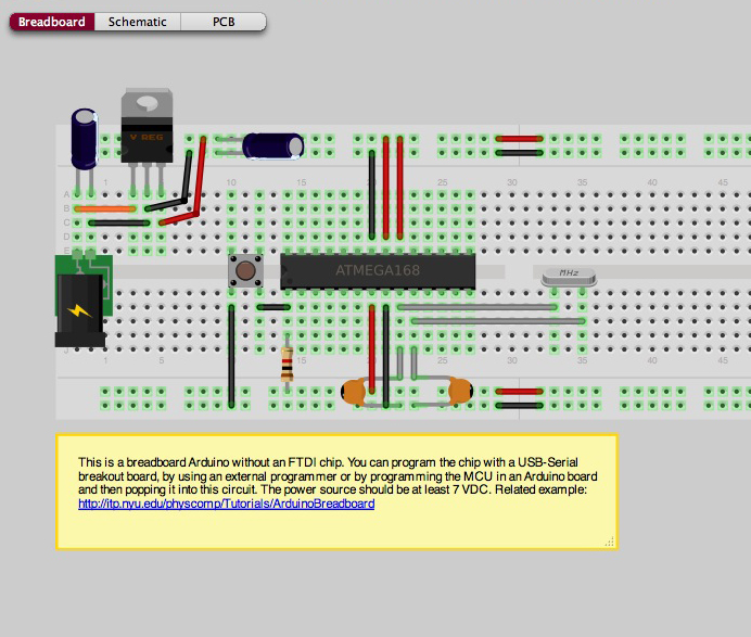
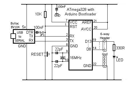
It is possible to construct a basic Arduino setup independently. This project illustrates a breadboarded Arduino configuration that does not utilize an FTDI chip, which implies the absence of USB connectivity. However, USB connectivity can be achieved through the...
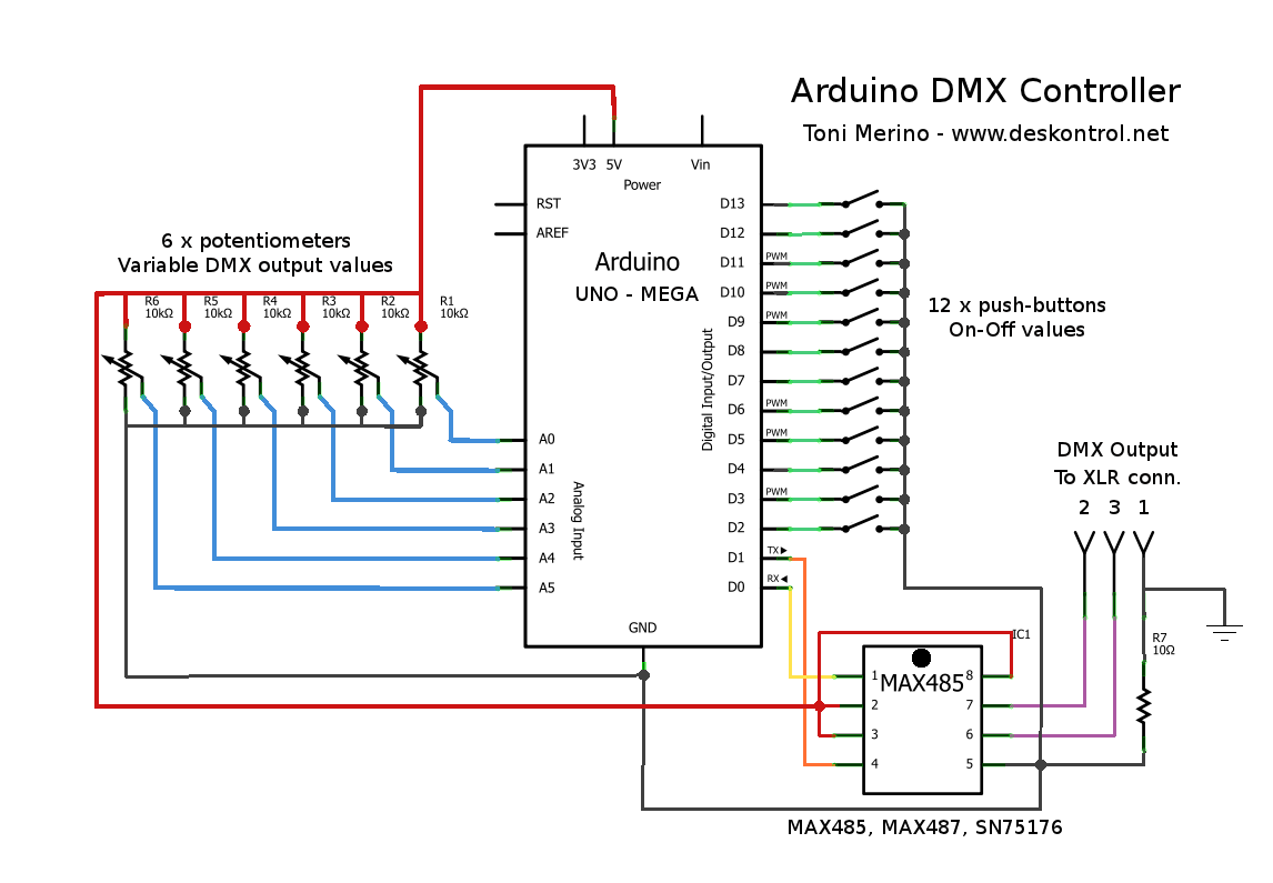
This document outlines the process of creating a compact and efficient Arduino DMX512 controller, which can be utilized to operate devices like a smoke machine via DMX or serve as testing equipment. The configuration includes six channels controlled by...
Software on a MacBook Pro includes Laidman & Katsura's WaveWindow, which functions as a software oscilloscope. It is beneficial for individuals working with sound on the Mac, offering an educational and entertaining experience. Additionally, Faberacoustical's Signal Scope allows for...
Connecting and programming the TA8050 DC motor controller with the Arduino microcontroller. The TA8050 is a versatile DC motor controller designed for use with microcontrollers, such as the Arduino. This controller allows for precise control of DC motors, making it...
A video switcher can be controlled using the computer's parallel port. However, as fewer PCs are equipped with parallel ports, and laptops do not typically have them, the need to control the switcher through a USB port has become...