
Arduino on a prototype board

The USB to RS232 converter, designated as USB-2-bot, serves as a crucial interface for programming and uploading sketches to Arduino-compatible boards. This converter can be substituted with various other models, such as the USB-TTL-232 cable from Adafruit, which also meets the necessary specifications for serial communication.
The circuit features an In-System Programming (ISP) connector that allows direct programming of the microcontroller's bootloader. This is essential for users who either build their own Arduino boards or need to reprogram existing ones. The ISP connector facilitates the loading of the bootloader onto the microcontroller, ensuring that it can communicate effectively with the Arduino IDE.
A key component of the circuit is the capacitor connected to the RTS (Request to Send) line on pin 1 of the serial connection. This capacitor is critical for enabling the auto-reset function, which automatically resets the microcontroller during the upload process. This feature streamlines the programming workflow by eliminating the need for manual resets.
The board is designed to be fully compatible with Arduino features, meaning it can work seamlessly with existing Arduino libraries and sketches. It is important to note that all standard Arduino boards come pre-installed with a bootloader. However, for custom-built boards, the user must program the bootloader onto the chip at least once, which emphasizes the necessity of the ISP programmer.
When working with bootloaders, users may encounter various options and configurations that can affect the functionality of the microcontroller. For instance, the ADABOOT bootloader, a modified version of the original bootloader, provides enhanced features, such as immediate sketch execution following upload. However, users may face challenges, such as read timeouts when interfacing with the Arduino IDE, which could stem from incorrect fuse settings or bootloader compatibility issues.
The fuses in AVR microcontrollers, such as the ATmega8, are critical for configuring operational parameters, including the choice between an external crystal oscillator or an internal clock source. These fuses are represented in binary format, where programmed bits are indicated by zeros and unprogrammed bits by ones. Careful attention is required during fuse programming, as incorrect settings can render the microcontroller inoperable, necessitating recovery procedures.
For users seeking a reliable bootloader, the one included with the Arduino IDE, specifically ATmegaBOOT.c, is recommended. This bootloader can be compiled using standard tools or utilized in its precompiled form, ensuring compatibility with the Arduino programming environment. Adjustments to the Makefile may be necessary to accommodate specific directory structures, facilitating a smooth compilation process.The USB to RS232 converter is called USB-2-bot and comes from another project. Any other converter would work as well, e.g. this USB-TTL-232-cable from adafruit. It has an ISP connector to program the bootloader and a serial connection used for uploading Arduino sketches. Also in place is a capacitor for the auto-reset function. It is connected to RTS line on pin 1 of the serial connection. The board should be feature compatible with Arduino. All Arduinos are comming with an installed bootloader. If you build it yourself, you have to program the chip with a bootloader, at least once. That is why we need the ISP programmer. First I tried to use the ADABOOT bootloader which is a modified version of the original bootloader. It has some modifications that makes it more comfortable, e.g. starts your sketch right after the upload is finished, without having to wait several seconds. Unfortunately I could not get it to work. I was able to compile it after adding some special #defines for the ATmega8. Programming it worked as well. I can see that the bootloader runs, as it blinks the LED four times, but it wont connect to the Arduino IDE. It always gets a read timeout. Next thing is to get the fuses right. If you are new to AVR microcontrollers, these fuses are used to configure some properties of the AVR chip, e.g.
which clock to use: an external crystal or the internal oscillator. These fuses are registers that can be programmed, just as you can program flash memory. Programming the fuses is always fun. Every option you want to enable or disable is represented as a bit and grouped in two 8 bit values, high fuse and low fuse (for ATmega8). To make it hard to read, programmed bits are represented by zeros and unprogrammed by ones. To make it more fun, if you mix things up, you can brick” your controller and it can get hard to revive it.
And because you probably do fuse programming only once per chip, you may have forgotten most of it when you have to do it again. So I took the bootloader that came with the Arduino IDE. It can be found at /arduino-0010/hardware/bootloaders/atmega8/ATmegaBOOT.c. You can try to call make to compile the bootloader or take the precompiled ATmegaBOOT.hex file. I needed to adapt the DIRAVR path setting in the Makefile to make it work. 🔗 External reference
Related Circuits
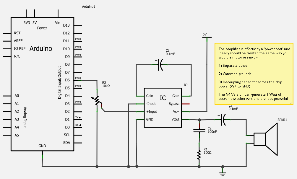
A simple solution for enhancing sound output from a microcontroller is the LM386 series of amplifier chips, which provide high-quality audio for under one dollar. These chips can be used to create a functional MP3 docking station and serve...

It has been determined that the Hijack method for obtaining serial data from the Mindflex to the iPhone will likely not be utilized. This decision is primarily based on the availability of most components needed to construct a similar...
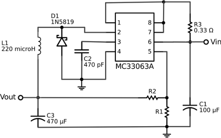
The voltage regulator integrated into the Arduino Uno is a linear-type regulator, which exhibits poor efficiency. When operating the ATmega238 at 5V with a 9V battery, nearly half of the battery's energy is wasted as heat by the regulator....
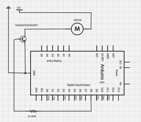
The BC547 transistor has a maximum operating current of 100 mA and a maximum voltage rating of 65 volts. When oriented with the label facing the viewer, the three terminals from left to right are collector, base, and emitter....
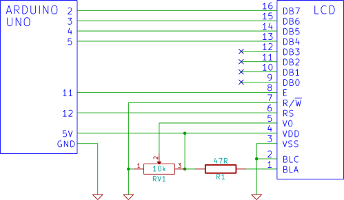
This tutorial demonstrates how to connect an LCD display to an Arduino and test it. It provides a step-by-step guide for beginners on using a breadboard to establish the connection. To connect an LCD display to an Arduino, first gather...
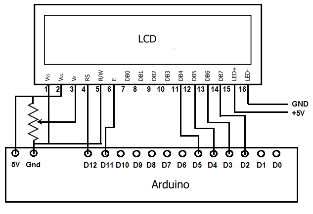
To achieve this, the first step involves establishing the necessary physical connections between the Arduino board and the LCD. Following this, code must be written to display the desired text on the LCD. LCDs have become the standard means...