
arduino + optotriac based ac dimmer blinking severely
```cpp
unsigned int i = 1;
void setup() {
Serial.begin(9600);
pinMode(AC_pin, OUTPUT);
pinMode(11, OUTPUT);
attachInterrupt(0, light, RISING);
}
void light() {
i++;
digitalWrite(11, LOW);
delayMicroseconds(10);
digitalWrite(11, HIGH);
}
void loop() {
if (i % 100 == 0) {
Serial.println("100");
i = 1;
}
}
```
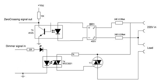
The results show that the code tests the zero-crossing circuit by counting up to 100 and printing a value (100) when it reaches that count. When the system runs without a load (with pin 11 not connected to the opto-triac), it provides a nearly perfect print rate of one per second, visibly steady. However, when pin 11 is connected to the opto-triac (MOC3021), the output load bulb begins to blink inconsistently, and the output from the optocoupler (4N25) becomes erratic, not outputting every second but instead appearing random. It is important to note that instead of MOC3021, an EL3021 is being used, and a BT136 triac is used in place of the TIC206. Currently, there is no snubber circuit in use. Previous attempts with different software have not resolved the issue, although the provided schematic differs slightly in terms of biasing, the exact values from the attached schematic are being utilized. Assistance is requested to resolve this problem.
The described circuit involves a microcontroller interfacing with an opto-isolator and a triac to control an AC load. The microcontroller is programmed to count and print a message at regular intervals, relying on an interrupt service routine (ISR) to manage the timing of the output signal. The use of an EL3021 opto-isolator instead of the MOC3021 may introduce variations in the switching characteristics, affecting the performance of the overall circuit.
In this configuration, the opto-isolator serves to safely interface the low-voltage control signal from the microcontroller with the higher-voltage AC load. The BT136 triac is intended to switch the AC load on and off based on the control signal provided by the opto-isolator. The blinking behavior observed may be attributed to several factors, including the lack of a snubber circuit, which is typically used to suppress voltage transients that can occur when switching inductive loads. The absence of this component might lead to instability in the control signal, resulting in the erratic blinking of the load.
To troubleshoot this issue, it is advisable to examine the timing and characteristics of the signals being generated by the microcontroller and opto-isolator. Verifying the connections and ensuring that the correct components are used according to the specifications of the circuit is essential. Additionally, implementing a snubber circuit across the triac could help mitigate any voltage spikes and improve the stability of the output signal.
Furthermore, it may be beneficial to review the interrupt handling within the microcontroller code to ensure that it is not being disrupted by other processes. The use of debouncing techniques or additional filtering may also be considered to enhance the performance of the circuit. By addressing these factors, the overall functionality of the circuit can be improved, leading to a more stable dimming control of the AC load.The light is simply blinking instead of dimming. So I used the following software to just glow the bulb without dimming: unsigned int i=1; void setup() { Serial. begin(9600); pinMode(AC_pin, OUTPUT); pinMode(11, OUTPUT); attachInterrupt(0, light, RISING); } void light(){ i+; digitalWrite(11, LOW); delayMicroseconds(10); digitalWrite(11, HIGH); } void loop(){ if(i%100=0){ Serial.
println("100"); i=1; } } Following are the results: In the above code I am testing the zero crossing circuit just by counting upto 100, and printing a value (100) when it turns hundred. When i run the system without load (pin 11 is not connected to opto triac) it gives me almost perfect print rate of 1 per second (visibly) and steady.
Now if i connect pin 11 to opto triac 3021, the output load bulb starts blinking (not steady at all), and also the output of optocoupler (4n25) gets randomized; Visibily i can see it is not giving output at every 1 second, rather it is somewhat random. Please note instead of MOC3021 i am using EL3021, and in place of TIC206 triac i used bt 136. I am not using any snubber right now. I also tried the software from. Still with no luck however their schematic is little bit different in terms of biasing but i am using exact values from the schematic attached.
Please help me sorting out this problem. 🔗 External reference
Related Circuits
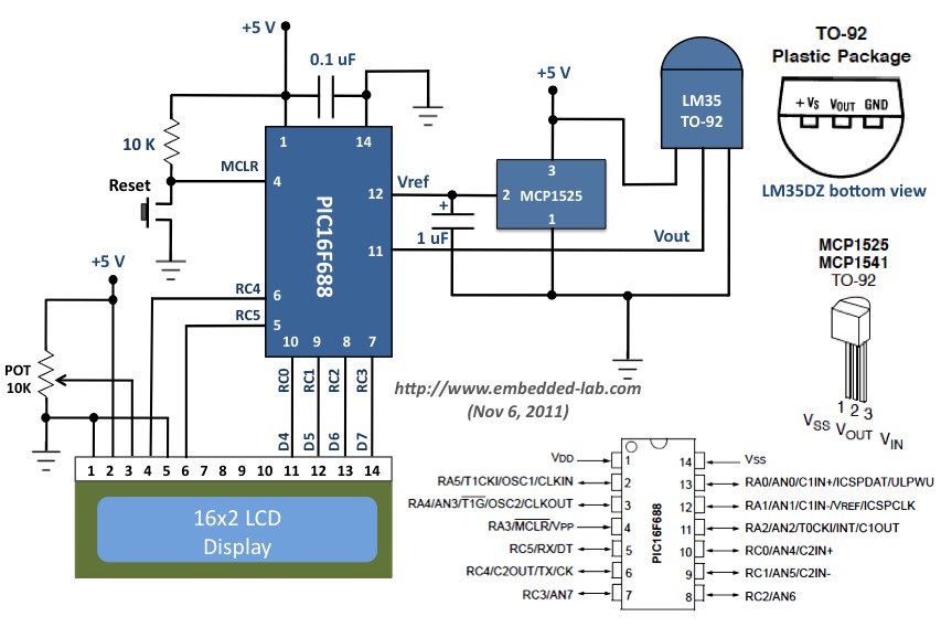
This document outlines a revised version of an LM35-based digital thermometer project previously shared. While it is a straightforward project, it remains popular among beginners learning about microcontrollers. The initial version contained a flaw, as some readers noted that...

An attempt at an Arduino guitar pedal. The guitar signal feeds through a PT2399 delay circuit, modified to include a JFET preamp phase. The delay circuit has Echo and Delay knobs. From there, it feeds into an optoisolated-Arduino-5V preamp,...
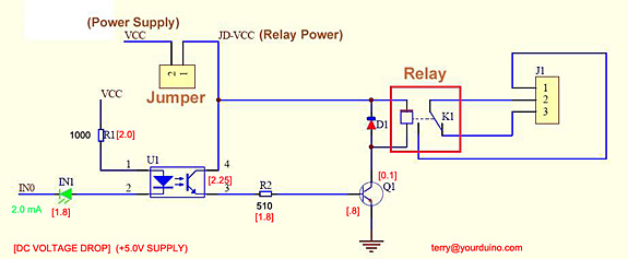
Control a relay from an Arduino-compatible board. When attempting to activate the relay from the Arduino, it takes at least a second to close, and sometimes it does not close at all. Digital pin 2 of the Arduino is...
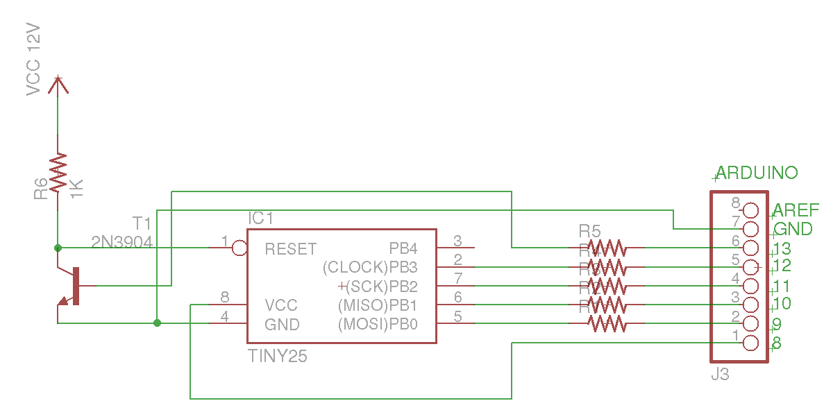
This Arduino sketch is designed to recover ATtiny microcontrollers that have become non-functional due to incorrect fuse settings. It achieves this by placing the affected ATtiny into high-voltage serial programming mode and rewriting the fuses to safe values. The...
The 8051 controller is mask-programmable, meaning it is programmed during manufacturing and cannot be reprogrammed afterward. However, the AT89C51 microcontroller, a derivative of the 8051, is reprogrammable. This device includes a timer, a serial port interface, and interrupt control,...

The super dimmer is an improved version compared to the standard dimmer currently in use. Testing its performance will provide a clearer understanding of its advantages. The super dimmer operates using advanced technology that allows for finer control over...