
Revised version of LM35 based digital temperature meter
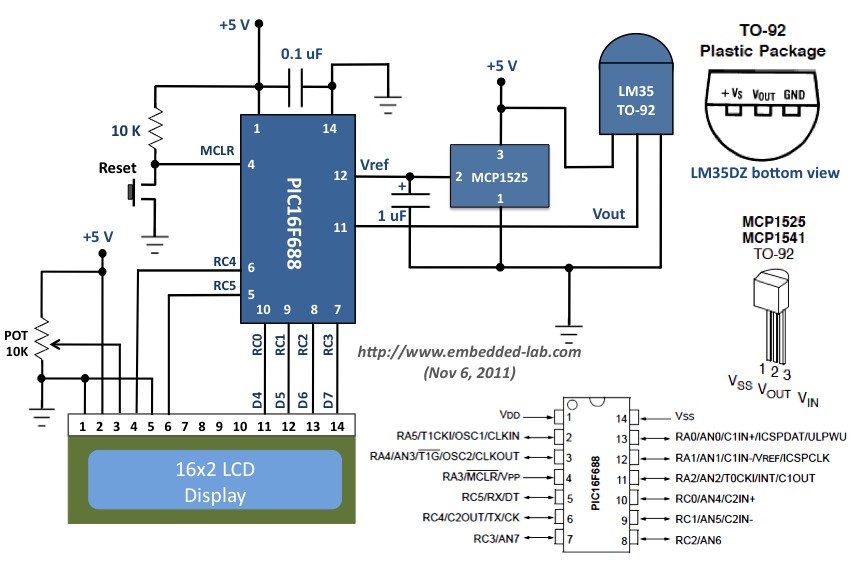
The circuit design features the LM35 temperature sensor connected to the analog input of the PIC16F688 microcontroller. The output of the LM35 sensor is fed into one of the ADC channels of the microcontroller, which is configured to read the voltage output corresponding to the temperature. The MCP1525 voltage reference IC is connected to the reference input of the ADC, ensuring that the conversion process is accurate and reliable.
The MCP1525 is powered by the same supply voltage as the microcontroller, ensuring compatibility and stability. The output voltage from the MCP1525 is precisely 2.5 V, which is above the minimum requirement specified in the PIC16F688 datasheet. This setup not only enhances the accuracy of the A/D conversion but also improves the resolution, allowing for more precise temperature readings.
In the software implementation, the microcontroller is programmed to convert the analog voltage reading from the LM35 sensor into a digital value using the configured ADC settings. The resulting digital value is then processed to convert it into a temperature reading in degrees Celsius. The LCD display is utilized to present the temperature readings to the user in a clear and readable format.
The overall design emphasizes simplicity, making it accessible for beginners while ensuring that the project adheres to best practices in electronic design. The use of stable reference voltage and straightforward programming techniques contributes to a reliable and effective digital thermometer.This is a revised version of my LM35 based digital thermometer project that I posted last year. Although it is one of the simplest projects, it is very popular among newbies who are just starting to learn microcontrollers. There was a little flaw in the original project as pointed by some readers. I was using a 1. 2 V reference for A/D conversion w ith PIC16F688 microcontroller. However, the PIC16F688 datasheet says Vref should be equal to or higher than 2. 2 V to ensure 1 LSB accuracy of A/D conversion. Here, I am rewriting the same project but this time I am using a MCP1525 IC to generate a precise 2. 5 V reference for A/D conversion. This will improve the accuracy of temperature measurements. The LM35 series of analog temperature sensors are produced by National Semiconductor Corporation and are rated to operate over a -55 °C to 150 °C temperature range. These sensors do not require any external calibration. The output voltage is proportional to the temperature, and the temperature-to-voltage conversion factor is 10 mV per °C.
The sensor does not have any DC offset output voltage (which means the output is 0V at 0 °C temperature) and therefore, a negative voltage source is required in order to measure temperatures below 0 °C. For simplicity, the setup shown here is made to measure temperatures above 0 °C only. The PIC16F688 microcontroller reads the analog output voltage from the sensor through one of its ADC channel and derives the temperature information out of it.
For the maximum temperature value of 150 °C, the output voltage of the sensor would be 150 x 10 mV = 1. 5 V. If we use Vref = 5. 0 V (power supply voltage) for A/D conversion, the resolution would be poor as the input signal goes only up to 1.
5 V. Besides, if the supply voltage is not stable, it won`t be a good idea to use it asVref for A/D conversion. Using a lower and more stable Vref voltage can improve both the resolution and the accuracy of A/D measurements.
However, the datasheet of PIC16F688 microcontroller recommends to use reference voltage above 2. 2 V to ensure 1 LSB accuracy of A/D conversion. The MCP1525 IC from Microchip provides a precise output voltage of 2. 5 V, which could serve this purpose. This device is also available in TO-92 package, and therefore, it can be wired on a breadboard too. The revised circuit diagram of the project is shown below. All the connections remain the same, except the two diodes and a resistor in the original circuit are replaced by a MCP1525 device. The whole setup of this project is shown below. For illustrative purpose, I am using the LCD display from my I/O board project here. Don`t get confused with all the LEDs and tact switches on the board, they should be disregarded. I am only using the LCD part of it. Floating point math can be avoided in programming to simplify the arithmetic. The complete program (source and HEX files) written in mikroC Pro for PIC can be downloaded from the following link.
🔗 External reference
Related Circuits
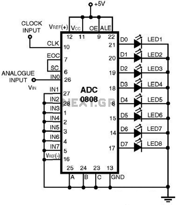
This is a straightforward analog-to-digital converter circuit utilizing an 8-bit analog-to-digital converter (ADC0808). Typically, an analog-to-digital converter (A/D Converter / ADC) necessitates interfacing with a microprocessor to convert analog signals. The ADC0808 is a widely used 8-bit A/D converter that...
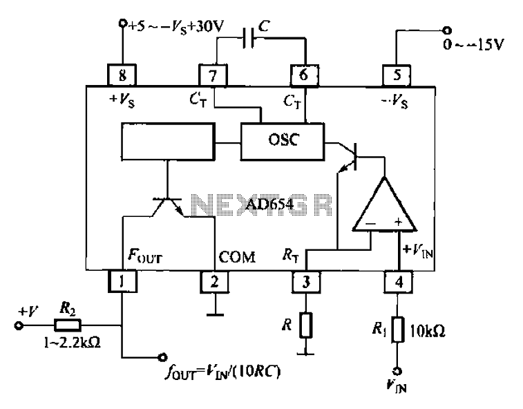
The AD654 voltage-frequency converter is a low-cost device that operates with a single supply voltage ranging from +5V to +36V, as well as with dual supplies of +5V to +18V. It can handle a maximum input voltage of 36V...
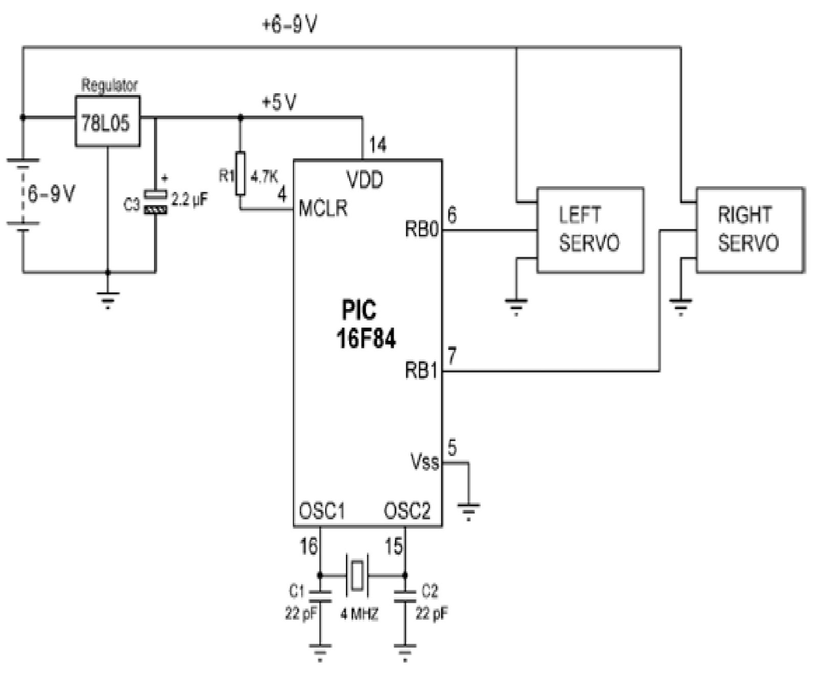
Mobile robots are utilized in various industrial, commercial, research, and hobby applications. This project focuses on controlling a mobile robot using servomotors. The robot is based on a well-known mobile robot called Boe Bot, developed by Parallax. The basic...
There are two differing opinions regarding the charging of alkaline batteries. Some assert that charging is effective, while others caution against it due to the risk of explosion. It is acknowledged that rechargeable alkaline batteries can typically endure 30...
This is a low-power voltmeter circuit suitable for alternative energy systems operating on 12-volt and 24-volt batteries. The voltmeter features an expanded scale design, allowing it to display small voltage increments within the 10 to 16-volt range for 12-volt...
A sensitive and reliable RF field strength meter is an invaluable instrument in amateur radio and in the radio-controlled model area. A field strength meter is. A radio frequency (RF) field strength meter is a specialized device used to measure...