
Arduino Power
To facilitate connections, plug small wires or pins into the Arduino and into a solderless breadboard, where other devices can be connected. A circuit board, often referred to as a "Shield," can be mounted on top of the Arduino, utilizing most or all of its pins. These Shields are typically designed for specific tasks, such as controlling motors or connecting to the Internet. Additionally, a "Sensor Shield" can be used to easily connect various devices to all of the Arduino's I/O, Analog, and Communications ports.
In practical examples, when the Blink program is operational, a small LED will blink on the Arduino. By attaching a Sensor Shield and connecting an Electronic Brick with a short cable, another LED on the relay brick will blink in sync with the Arduino's LED. The relay, which functions as a switch operated by an electromagnet, is controlled by the Arduino through a digital I/O pin. The Electronic Brick system simplifies the connection of multiple devices to the Arduino for testing and development.
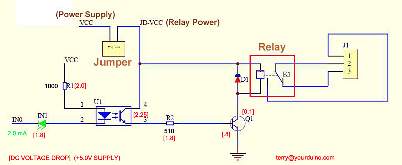
The Relay Brick features a standard cable connector with labels for Ground, Voltage, and Signal. The relay operates with a +5V supply, flowing through a 10,000-ohm resistor to the base of a transistor, which activates the relay. The current gain of the transistor allows it to control the relay with minimal input current. An LED connected across the electromagnet illuminates when the relay is activated.
The relay's internal switch connects the Common (COM) terminal to the Normally Closed (NC) contact when off. Activating the relay switches the connection to the Normally Open (NO) terminal. This setup can be utilized to control devices such as lamps. For more complex applications, such as aquarium systems or home energy management, multiple relays may be required.
The initialization sequence in the Arduino program is crucial, as the relay controls are Active LOW, meaning a LOW signal turns them ON. To prevent unintended activation during power-on or reset, the setup ensures all relays remain inactive until the program is ready.
An example program demonstrates the control of four relays on a relay board, ensuring proper initialization and sequential activation of the relays. The example includes necessary libraries, constant declarations, and pin assignments for Arduino I/O.
For advanced applications, an 8-relay board with optical isolation can be used, allowing the Arduino to control the relays without direct electrical connections. This feature enhances safety when controlling equipment with separate power supplies. The board provides options for power supply configuration, requiring careful attention to connections to ensure proper operation.
Relay boards can be employed to manage various loads, including lights, valves, and ventilation systems. With the integration of sensors and software sketches, complex and intelligent control systems can be developed. However, care must be taken to mitigate potential Electromagnetic Interference, which may disrupt the Arduino's operation. Further information on addressing these issues is available through additional resources.Having your Arduino control higher-power devices like lights, motors, pumps, doors, and many more is one of the most interesting and useful applications you may get involved with. But it can be a little difficult and possibly dangerous when power line voltages are being controlled.
There are significant differences in controlling AC power compared to DC. And there are considerations about different kinds of loads and so forth. This section will cover many of these subjects, show several available devices you can connect to Arduino to control power (examples above), and provide examples of working projects. (Please direct questions, critiques and suggestions to: terry@yourduino. com ) NOTE: Sometimes switching lights, motors, etc. with relays can cause Electromagnetic Interference (EMI). More information about what to do in these cases is available HERE: Get your Arduino plugged into your main computer, and download the Good Old Blink Program.
If you need help getting started, go here. You should have the LED on your Arduino blinking ON for 1 second, OFF for 1 second. If you`re pretty familiar with those words and ideas, fine. But if you`d like to learn a little more before we continue, jump over here and then come back. Plug small wires or pins on the ends of wires into the Arduino and then into a "Solderless Breadboard" where other devices can be plugged in and connections made. (Example) Plug a circuit board (usually called a "Shield") on top of Arduino, plugging into most or all Arduino pins.
These Shields are usually special-purpose add-ons to Arduino to do things like control robot motors, connect to the Internet, etc. (Example). Plug a special "Sensor Shield" (Example) on top of Arduino. Then you can easily plug cables and other devices into all the Arduino I/O, Analog and Communications ports.
You can also plug in cables from many different devices in the form of "Electronic Bricks" (Example), to quickly try out different options and test and develop software. We`ll use this in our next examples. OK, if you have the Blink program running, a small LED is blinking on your Arduino. Here, we have plugged a Sensor Shield on top of the Arduino, and plugged in a small Electronic Brick with a short cable.
Now there is a small LED ("L" on the red relay brick) blinking on and off the same as the LED on Arduino. And if you listen you can hear the relay clicking on and off too. A Relay is a switch that is operated by an electromagnet. (More about relays). In this example, our Arduino has the very easy job of driving a 10, 000 ohm resistance with Digital I/O Pin 13.
The Electronic Brick system is an easy way to connect dozens of different devices to Arduino and try them out or make working systems. But you can make many of these circuits yourself if you want, and they are good examples. Let`s look in more detail at the Relay Brick: First, notice the cable connector has a standard pattern of wires: Ground-Voltage-Signal (see the GVS labels on the Sensor Shield above).
So the brick has +5 volt power available. Here`s what happens: +5 volts flow through 10, 000 ohm resistor R1 to the Base of transistor Q1, and a current of about. 0005 amps (500 microamps) flows and turns the transistor ON. The transistor connects one end of the electromagnet inside the relay to Ground (the other end is already connected to 5 volts), and a current of about.
07 amps flows. We say the transistor has a Current Gain of more than 100. Details: An LED and it`s current limiting resistor are also connected across the electromagnet and it lights up when the relay is turned on. Just for you. Look at the diagram on the right. This shows the switch that is inside the relay. This switch is "thrown" by the electromagnet inside. The diagram shows that COM is connected to the Normally Closed contact. That`s the case when the relay is off. When the relay is turned on the electromagnet flips the switch up and COM is then connected to Normally Open.
So, if we want a lamp to be on when the relay is on, we connect our circuit from COM to NO. Let`s try that out. OK, we have the relay clicking on and off. Inside, the COM terminal is connected to the NO (Normally Open) terminal when the relay is on. So all we have to do is use that switch to turn the lamp on and off. If you do something a little bit more complex, like controlling an aquarium, a plant growing system, or a home energy management system, you`ll need more relays. Let`s look more closely at the 4-relay and 8-relay boards shown in the top of page photo. (You can get them here). And you can see their schematic diagrams on the product pages. You can build these circuits yourself if you wish, or prototype things like the examples here. IMPORTANT NOTE: There is a issue with start-up of Arduino programs that control these relays. These relays input controls are Active LOW, meaning that setting a pin LOW turns them ON. To assure that no relays activate at Reset or Power-On until you want them to, the initialization sequence in SETUP should be: This design is intentional, so that it is possible to guarantee that at power-on of a system, or system reset, that no relays activate except when expected under program control.
There may be pumps, lights etc attached and chaos could ensue if this was not controlled definitively for each output port being used. Then in the main Loop section turn relays On or Off as needed. Following is an example program that properly controls 4 relays on our 4-relay board ( Available HERE ) /* YourDuino Example: Relay Control 1.
10 Handles "Relay is active-low" to assure no relay activation from reset until application is ready. terry@yourduino. com */ /*-( Import needed libraries )-*/ /*-( Declare Constants )-*/ #define RELAY_ON 0 #define RELAY_OFF 1 /*-( Declare objects )-*/ /*-( Declare Variables )-*/ #define Relay_1 2 // Arduino Digital I/O pin number #define Relay_2 3 #define Relay_3 4 #define Relay_4 5 void setup() /* SETUP: RUNS ONCE */ { //-( Initialize Pins so relays are inactive at reset)- digitalWrite(Relay_1, RELAY_OFF); digitalWrite(Relay_2, RELAY_OFF); digitalWrite(Relay_3, RELAY_OFF); digitalWrite(Relay_4, RELAY_OFF); //-( THEN set pins as outputs )- pinMode(Relay_1, OUTPUT); pinMode(Relay_2, OUTPUT); pinMode(Relay_3, OUTPUT); pinMode(Relay_4, OUTPUT); delay(4000); //Check that all relays are inactive at Reset }//-(end setup )- void loop() /* LOOP: RUNS CONSTANTLY */ { //-( Turn all 4 relays ON in sequence)- digitalWrite(Relay_1, RELAY_ON);// set the Relay ON delay(1000); // wait for a second digitalWrite(Relay_2, RELAY_ON);// set the Relay ON delay(1000); // wait for a second digitalWrite(Relay_3, RELAY_ON);// set the Relay ON delay(1000); // wait for a second digitalWrite(Relay_4, RELAY_ON);// set the Relay ON delay(4000); // wait see all relays ON //-( Turn all 4 relays OFF in sequence)- digitalWrite(Relay_1, RELAY_OFF);// set the Relay OFF delay(1000); // wait for a second digitalWrite(Relay_2, RELAY_OFF);// set the Relay OFF delay(1000); // wait for a second digitalWrite(Relay_3, RELAY_OFF);// set the Relay OFF delay(1000); // wait for a second digitalWrite(Relay_4, RELAY_OFF);// set the Relay OFF delay(4000); // wait see all relays OFF }//-(end main loop )- //*( THE END )* It has the same relay as the Electronic Brick 1-relay board and basically the same transistor drive circuitry.
You would connect Arduino to the connector on the upper left. +5V to VCC, four input pins, and GND. There are LEDs on the board that show when a relay is active, and a green LED to show that +5V power is applied. Notice how our multicolor flat cable and Sensor Shield makes this easy to connect! Here is a different 8-relay board. (Available HERE) It has an added feature of Optical Isolation. This means that all Arduino really does is turn on an LED inside an IC package, and THAT turns the relay on.
So there does not need to be any direct connection between Arduino and the relay driver circuits. This can be an advantage and safety factor when controlling a separate piece of equipment that has it`s own power supplies and perhaps a metal case etc. The 8-relay board shown here gives you a choice of powering the relay drive circuits from the same supply as Arduino, or isolating Arduino by removing the jumper over at the right.
In that case you need to have some separate +5V supply connected to GND and the "JD-VCC" pin (whatever THAT label means. ). Here`s a closeup look at the pins: If you isolate Arduino, you need to connect +5V ONLY (NOT GND) from Arduino to the VCC pin.
The Arduino output pins go to IN1 through IN8. And again, these pins are Active LOW. It is possible to use these relay boards with 3. 3V signals, IF the JD-VCC(RelayPower) is provided from a +5V supply and the VCC to JD-VCC jumper is removed. . That 5V relay supply could be totally isolated from the 3. 3V device, or have a common ground IF opto-isolation is not needed. If used with isolated 3. 3V signals, VCC (To the input of the opto-isolators, next to the IN pins) should be connected to the 3.
3V device`s +3. 3V supply. You should test with your 3. 3V device to be sure. We will soon be testing with Arduino DUE and Raspberry Pi which are 3. 3V devices. You can control a lot of different lights, water valves, and ventilation systems with relays like this. With some sensors and your Software Sketch ideas, an intelligent system may be born. NOTE: Sometimes switching these kinds of loads can cause Electromagnetic Interference, Arduino lockup etc.
More information on handling these problems is available HERE: 🔗 External reference
Related Circuits

A circuit is needed to drive three or more LEDs at a current of 200-350mA each, with the capability to randomly flash or strobe them at a frequency of 5-20Hz. The input power should be low-voltage DC, with a...
One of the main features of the regulated power supply circuit being presented is that though fixed-voltage regulator LM7805 is used in the circuit, its output voltage is variable. This is achieved by connecting a potentiometer between common terminal...
Programming the GPS Disciplined Oscillator (GPSDO) with the QP state machine framework has revealed that the Arduino Mega 2560 system has run out of SRAM. This is not surprising given the limited 8 kB available, especially when programming in...
During experiments with various receivers and amplifiers powered by "free energy," it was discovered that connecting the audio amplifier to the receiver using only two wires for audio signals and supply voltage is more convenient. This setup allows the...
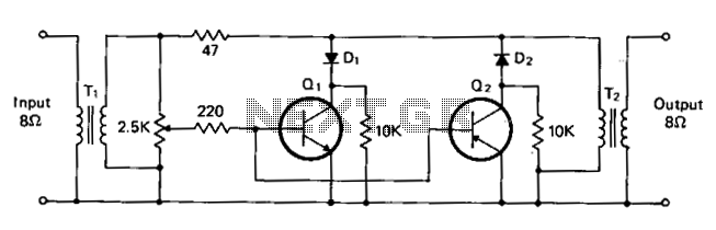
T1 and T2 are 600 to 8-ohm transformers (any transistor radio output transformers with 500 to 4-ohm impedance may be used). Q1 is a 2N2222 NPN transistor, and Q2 is a 2N2907 PNP transistor. D1 and D2 are 1N270...

The following circuit is an example of how to get power from an RS-232 serial port. It provides regulated +5V power for logic circuits and also unregulated positive and negative power supplies for the RS-232 transmitting circuit. The circuit...