
Random oscillator circuit for high power LEDs

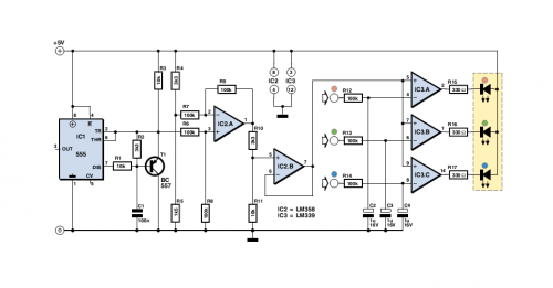
To achieve the desired functionality, a simple LED driver circuit can be designed using a combination of transistors, resistors, and a low-frequency oscillator. The circuit can utilize a 555 timer IC configured in astable mode to generate the required flashing frequency. The output of the timer will control the base of a power transistor, which will drive the LEDs.
The circuit can be powered by a low-voltage DC source, such as a battery or a DC power supply. The input voltage can be in the range of 3V to 12V, allowing flexibility in power source selection. The 555 timer will be configured with resistors and a capacitor to set the desired flashing frequency between 5Hz to 20Hz. By adjusting the resistor values, the duty cycle and frequency can be fine-tuned.
To drive the LEDs, a suitable power transistor (e.g., NPN or MOSFET) can be used. The collector (or drain) of the transistor will be connected to the cathode of the LEDs, while the anode will connect to the positive supply voltage. A current-limiting resistor should be placed in series with each LED to ensure that the current stays within the specified range of 200-350mA.
To enable random flashing, a simple random number generator circuit can be added, utilizing additional components such as diodes and capacitors to create a more complex timing mechanism that will randomly activate different LEDs at different intervals. This design allows for multiple LEDs to be lit simultaneously, depending on the random activation logic.
In summary, the proposed circuit design utilizes a 555 timer for frequency generation, a power transistor for LED driving, and additional components for random flashing capabilities, all while maintaining a low component count and flexibility in power supply voltage. This approach meets the requirements for a simple, cost-effective solution for driving multiple LEDs with random flashing behavior.I`m looking for a circuit (the simpler and cheaper, the better) that can drive three or more LEDs at 200-350mA each, randomly flashing/strobing them at 5-20Hz. Input power should be low-voltage DC. A range for Vin, instead of an exact 5.0V or whatever, would be a big plus. It`d be nice if the circuit could handle more than one LED being on simultaneously, but it`s not vital.
I don`t have any PIC programming stuff, and I`d rather use fewer components. If I`ve left out anything important,.. 🔗 External reference
Related Circuits
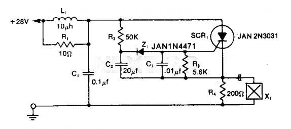
The LRC input network limits the anode dv/dt to a safe value below 30 V/μs. Rl provides critical damping to prevent voltage overshoot. While a simple RC filter section could be used, the high current required by the squib...
Electronic schematics collections provide a platform for discussions related to electronic circuit schematics, printed circuit board (PCB) diagrams, and various electronics projects. These collections serve as valuable resources for engineers, students, and hobbyists interested in electronics design and development. They...
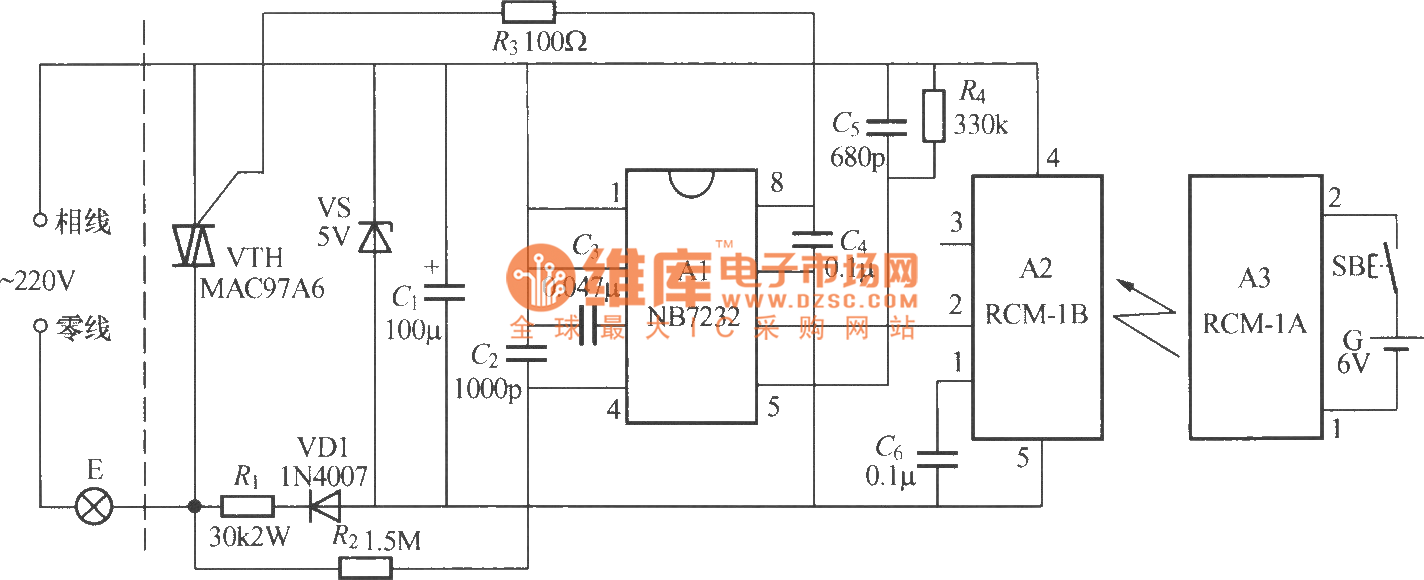
The diagram above illustrates a radio remote control dimmer circuit. This circuit utilizes a micro radio transmit/receive module in conjunction with a light modulation ASIC, resulting in a compact and easily producible design. It operates reliably and features a...
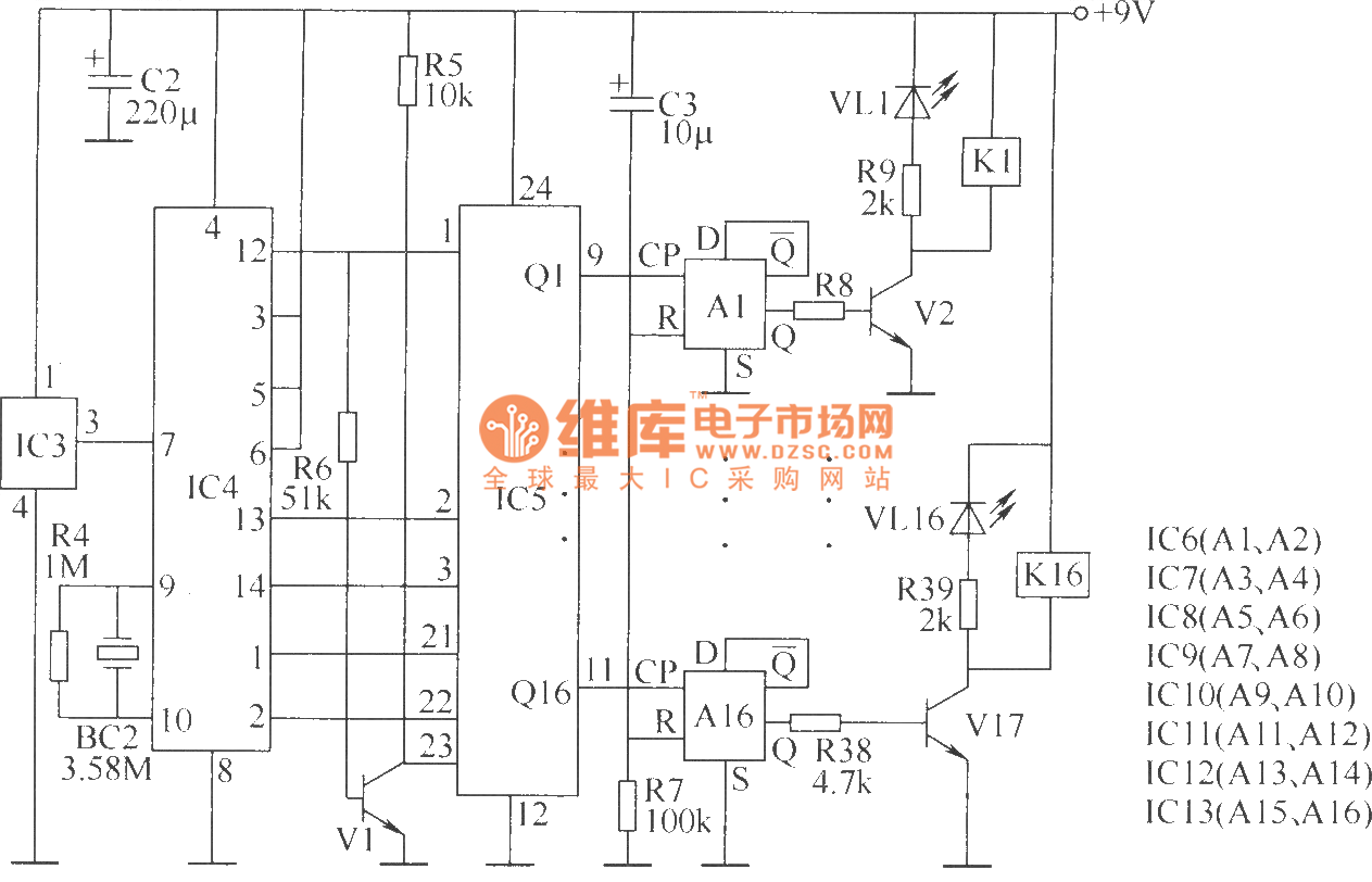
The wireless remote control transmitter circuit consists of control buttons S1 to S16, resistors R1 to R3, a capacitor C1, a regulator diode VS, a crystal oscillator BC1, and DTMF encoder integrated circuits IC1 and IC2. The circuit components...
This is a stereo power amplifier circuit that operates at up to 22W per channel, resulting in a total output of 2x22W. A few external components are required to support the main component, the TDA1554. A heatsink on the...
The gain control element is a Light Dependent Resistor (LDR). These are blessed with a few very useful features for our purposes, one of which is low distortion even at quite high signal levels. Being light activated, all we...