
arduino scanning backlight
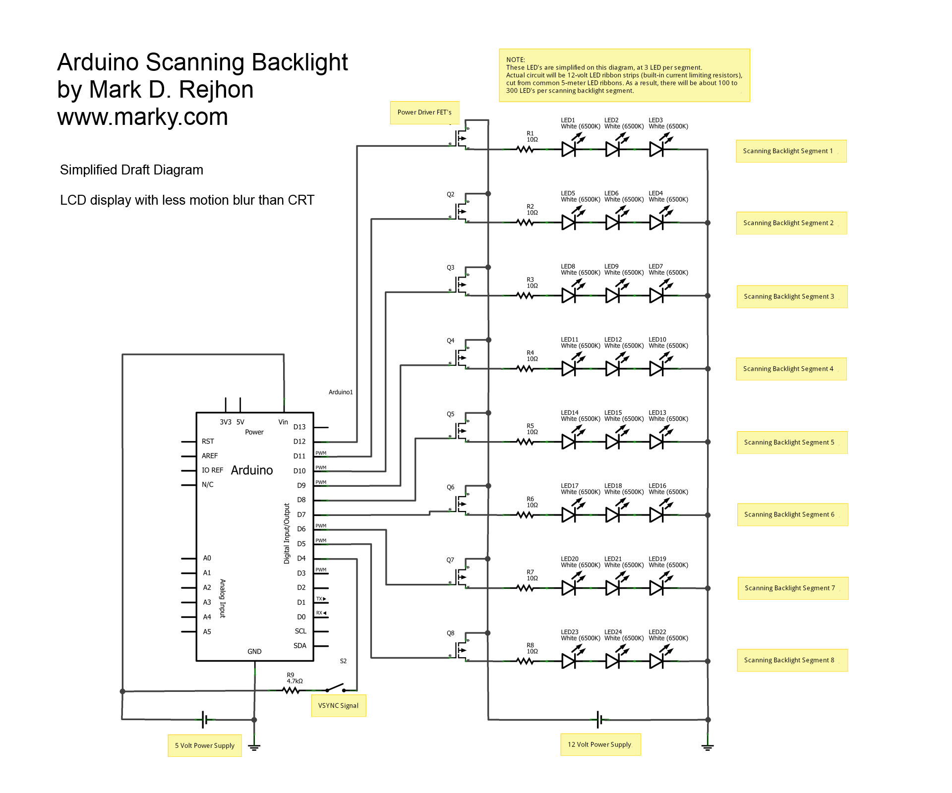
The schematic diagram outlines a system designed to enhance visual clarity by employing a backlight scanning technique. The core component is the Arduino microcontroller, which serves as the central processing unit for monitoring the VSYNC signal. This synchronization signal is crucial for aligning the backlight operation with the refresh rate of the display, thereby mitigating input lag.
The scanning sequence involves activating segments of the LED backlight in rapid succession, utilizing ultra-short strobe pulses. This method minimizes motion blur by ensuring that the backlight is only illuminated during the critical moments when the display is actively refreshing its image. The use of super bright LEDs ensures that each segment provides adequate illumination, even when pulsed at high frequencies.
To achieve the necessary brightness for these ultra-short strobe pulses, the design incorporates LED ribbons, which consist of numerous LEDs arranged in series. This configuration allows for a significant cumulative light output, surpassing that of single LED units. The ribbons are connected to the Arduino through appropriate driver circuits capable of handling the high current demands of the LEDs during operation.
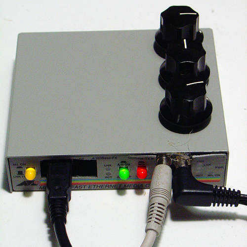
In summary, this schematic diagram represents a sophisticated approach to backlight management in display systems, combining the capabilities of the Arduino platform with high-efficiency LED technology to deliver an enhanced viewing experience through reduced motion blur and improved brightness.This is a simplified schematic diagram for a home-made scanning backlight driven by an Arduino, an open-source electronics prototyping platform. The Arduino monitors the VSYNC signal (input-lag compensated) and executes a backlight scanning sequence, using ultra-short strobes of super bright LED`s per segment.
This greatly reduces motion blur. For the brightness required for ultra-short strobes, reels of LED ribbons totalling thousands of LED`s will be used instead of individual LED`s. 🔗 External reference
Related Circuits
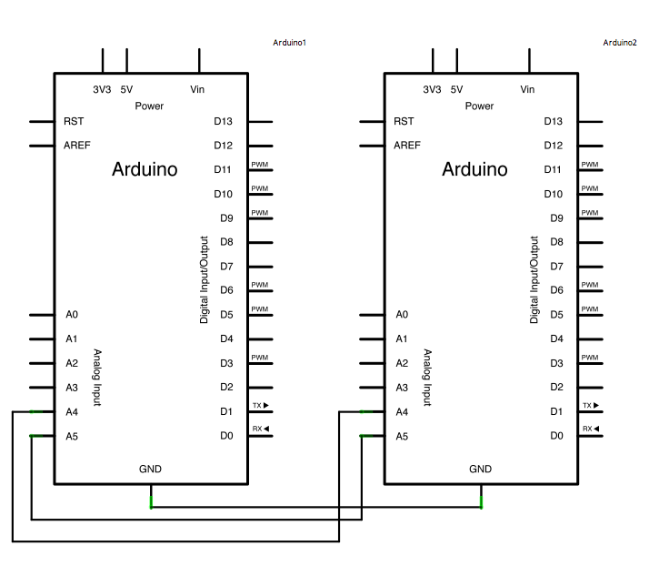
In certain scenarios, it can be beneficial to configure two or more Arduino boards to exchange information with each other. This example demonstrates a Master Reader/Slave Sender setup using the I2C synchronous serial protocol. The first Arduino, designated as...
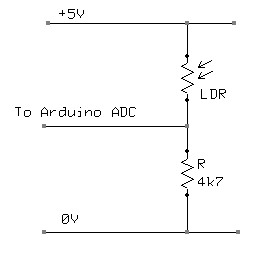
A Light Dependent Resistor (LDR) is utilized to create a simple nightlight for children's bedrooms that automatically turns on in darkness and off in light. The resistance of an LDR varies based on the light intensity it receives. In...
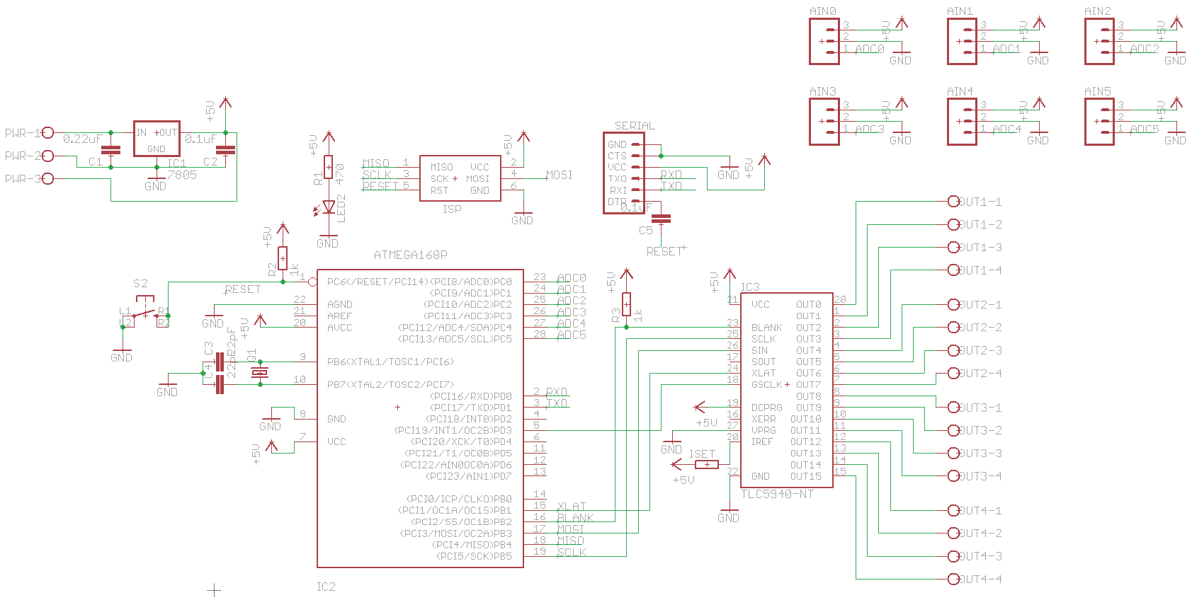
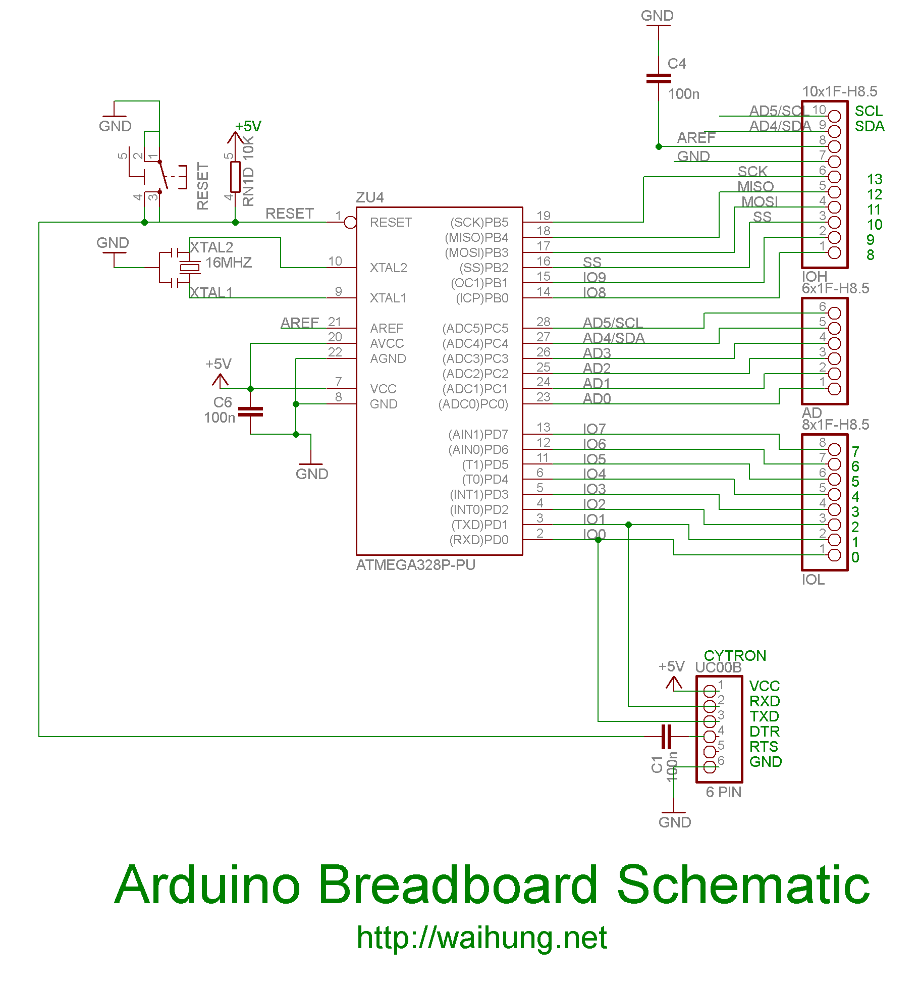
The initial step involves selecting software, and CadSoft Eagle was chosen due to the abundance of available tutorials, making it a suitable starting point. Once the process is understood, the choice of software can be reconsidered. For now, the...
Make your own Guitar Effects Pedal with an Arduino board. Bit crushing, rate reducing, weird noises. 10-bit effects/guitar pedal with an Arduino for lo-fi DSP The project involves designing a guitar effects pedal utilizing an Arduino microcontroller to create various...
On the Uno boards, there is an integrated circuit (IC) that functions as a USB to serial converter, enabling programming and communication with the Arduino from a computer. This IC is a surface-mounted device (SMD). The R3 version utilizes...
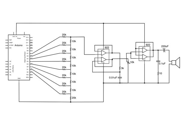
Generate sound or output analog voltages with an Arduino. This guide will demonstrate how to set up a basic digital-to-analog converter. To create a digital-to-analog converter (DAC) using an Arduino, one can utilize the Pulse Width Modulation (PWM) feature available...