
Arduino SD Cards and Datalogging

The project involves the integration of an SD card shield with a microcontroller to create a data logger capable of recording sensor data. The SD card shield serves as an interface for data storage, allowing for the reading and writing of data in a structured format. The microcontroller, typically an Arduino or similar platform, will handle the logic and control necessary for data acquisition from the sensors.
To begin, the wiring of the SD card shield to the microcontroller must be established. This typically involves connecting the SPI pins (MOSI, MISO, SCK) and a chip select (CS) pin, along with power and ground connections. The specific pin configuration can vary based on the microcontroller used and the design of the shield.
Once the hardware setup is complete, the software component involves initializing the SD card and establishing communication protocols. The microcontroller code will include libraries specific to SD card operations, enabling functions for file creation, data writing, and data reading. The sensors, which may include temperature, humidity, or pressure sensors, will be connected to the microcontroller's analog or digital input pins, depending on their output type.
The data logger will periodically read values from the sensors, format them appropriately, and write them to a file on the SD card. This process can be managed using timers or interrupts to ensure consistent data collection intervals. The recorded data will be stored in a CSV (Comma-Separated Values) format, which is compatible with data analysis tools such as Microsoft Excel.
The use of Fritzing to create circuit schematics allows for a visual representation of the connections and components involved in the project. It is advisable to refer to these schematics while implementing the project to ensure accurate wiring and component placement.
In summary, this project not only reinforces the fundamental concepts learned in previous tutorials but also provides practical experience in integrating various components to create a functional data logging system. The outcome will facilitate data collection and analysis, enhancing understanding of sensor behavior and data interpretation.Now that we`ve covered the basics in tutorials 1-10 (you have watched them all right! ), it`s time to start pursuing some more complex projects! In this episode, we`ll utilize an SD card shield from cooking-hacks. com to create a datalogger. First, I`ll walk you through the process of reading from, and writing to an SD card. Then, we`ll utilize som e of our knowledge from tutorials 4, 6, 7, and 8 to add several sensors that we can poll periodically using our datalogger. The logger will record sensor values to its SD card in a useful format so that we can later use a computer program like Microsoft Excel to visualize the data.
Download the schematics and source code first so you can reference them while you watch the video. For the first time, I`m using fritzing to draw the circuit schematics. So, take a look at them, and let me know what you think! 🔗 External reference
Related Circuits
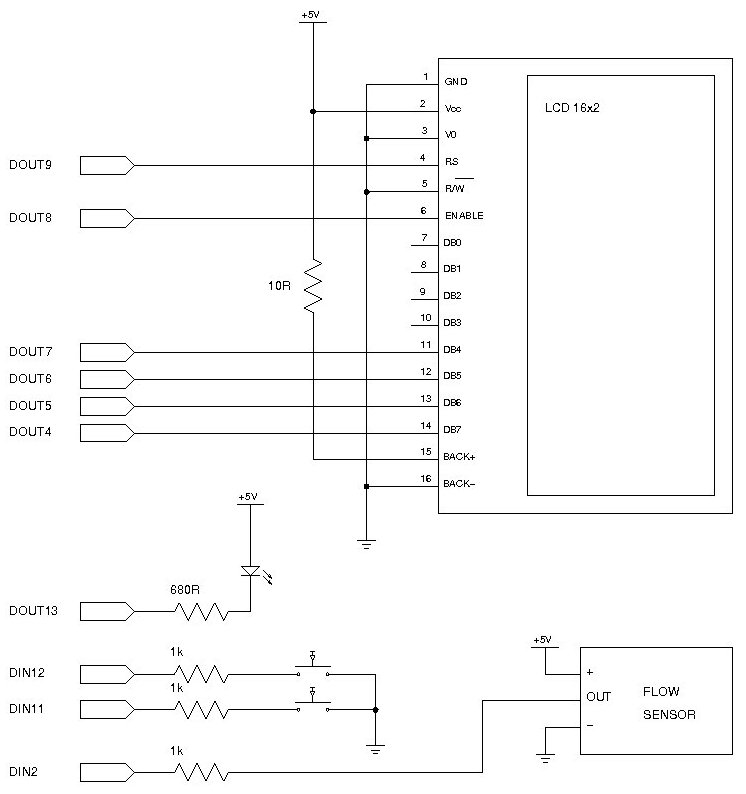
Measuring the consumption of a resource that has units by volume can be more challenging than it appears. Resources such as water, gas, and electricity are typically measured using gauges that determine either the instantaneous flow rate or the...
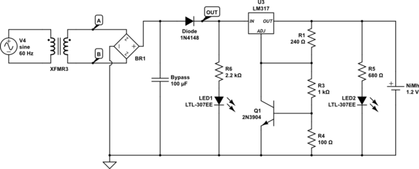
An Arduino powered by 2 or 4 rechargeable NiMH AA batteries is being developed. The choice of using two batteries is based on the intention to boost the voltage to meet the requirements. The main challenge is ensuring that...
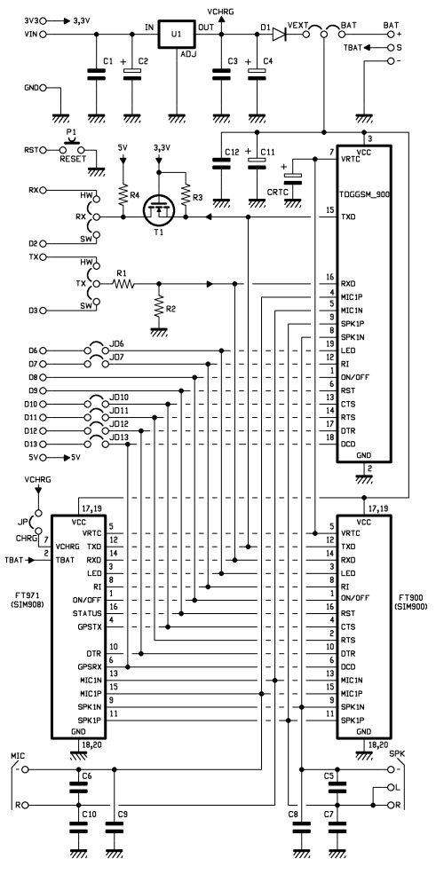
This shield for Arduino is designed based on the GSM/GPRS SIM900 module or the GSM/GPRS & GPS SIM908 module, enabling voice calls and data connections via GPRS. The supply circuit utilizes a simple LM7805 voltage regulator. To operate, it...
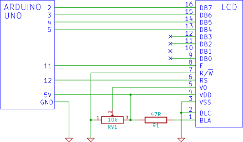
This tutorial demonstrates how to connect an LCD display to an Arduino and test it. It provides a step-by-step guide for beginners on using a breadboard to establish the connection. To connect an LCD display to an Arduino, first gather...
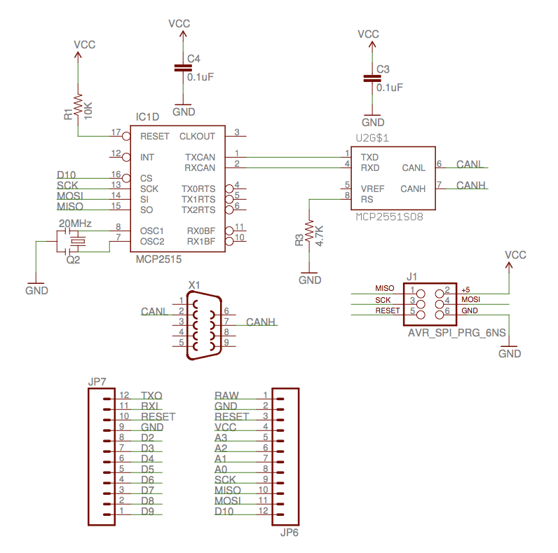
The implementation of the Controller Area Network (CAN) for aircraft applications is referred to as CAN-FIX, which is part of the MakerPlane Open Source Airplane project. This project aims to create an Arduino shield that facilitates communication over the...
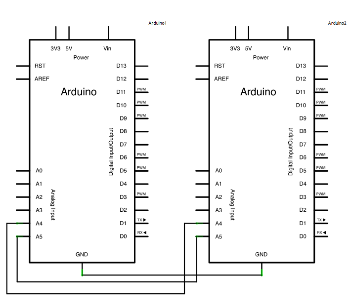
In certain scenarios, it can be beneficial to configure two or more Arduino boards to exchange information with each other. This example demonstrates a Master Reader/Slave Sender setup using the I2C synchronous serial protocol. The first Arduino, designated as...