
Arduino Serial Call Response

The described circuit implements a basic communication protocol between an Arduino microcontroller and a computer, facilitating the transmission of sensor data. Upon initialization, the Arduino sends a constant ASCII character 'A' to signal readiness and establish a communication link. The continuous transmission of this character persists until a serial response is detected, indicating that the computer is prepared to receive data.
Once the Arduino receives a response, it collects data from three analog sensors connected to pins A0 and A1. The sensors are connected through voltage dividers formed by 10K ohm resistors, which scale the sensor output to a range compatible with the Arduino's analog input. This ensures that the input voltage remains within the acceptable range for the ADC (Analog-to-Digital Converter) of the microcontroller, which typically operates from 0 to 5 volts.
In addition to the analog sensors, a pushbutton or switch is integrated into the circuit, connected to digital I/O pin 2. This component is also connected to ground through a 10K ohm resistor, which acts as a pull-down resistor. This configuration ensures that the pin reads a LOW state when the button is not pressed, and a HIGH state when the button is activated.
The overall functionality allows for interactive data collection and monitoring, enabling applications in various environments such as data logging, real-time monitoring, and control systems. The flexibility to interface with multiple software platforms, including Processing and Max/MSP, enhances the utility of this setup for both educational and professional projects involving sensor data analysis and visualization.This sketch sends an ASCII A (byte of value 65) on startup and repeats that until it gets a serial response from the computer. Then it sends three sensor values as single bytes, and waits for another response from the computer. You can use the Arduino serial monitor to view the sent data, or it can be read by Processing (see code below), Flash, PD
, Max/MSP (see example below), etc. Connect analog sensors to analog input pin 0 and 1 with 10K ohm resistors used as voltage dividers. Connect a pushbutton or switch to digital I/O pin 2 with a 10Kohm resistor as a reference to ground. 🔗 External reference
Related Circuits
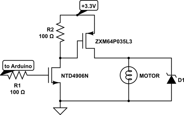
Charge a simple servo that only has + and - pins. Typically, the - pin is connected to ground, while the + pin is connected to a digital output from an Arduino. This setup works, but the servo operates...
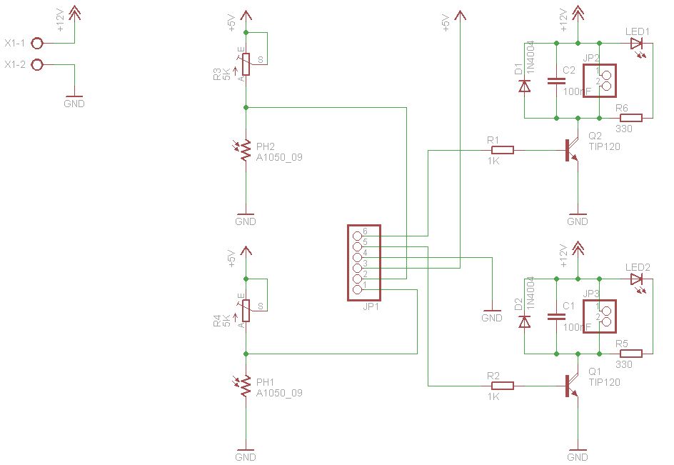
The figures above illustrate the fundamental concept of a robot, which comprises input and output devices connected to a central processing unit, often referred to as the brain. In this case, the Arduino acts as the brain, controlling all...
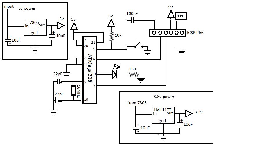
If you are interested in working with Arduino, you may have considered creating your own Arduino board. Creating a custom Arduino board can be an enriching project that allows for greater flexibility and personalization in electronic designs. The process typically...

The 040904C version of the code has a larger UART receive buffer and supports two pushbuttons that send either an ASCII "R" ($52) or an ASCII carriage. Something to keep in mind when using AVR controllers that support 16-bit...
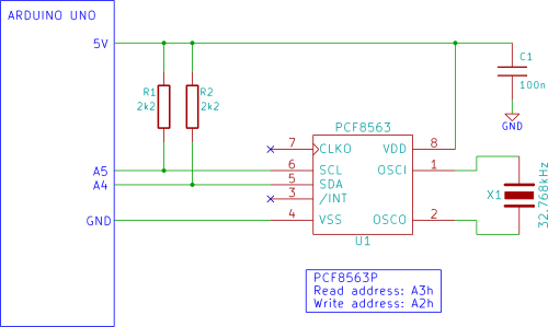
The Arduino displays the time and date on an optional LCD and in the Arduino IDE serial monitor window. A PCF8563 real-time clock (RTC) integrated circuit (IC) is utilized to generate the time and date. The time and date...
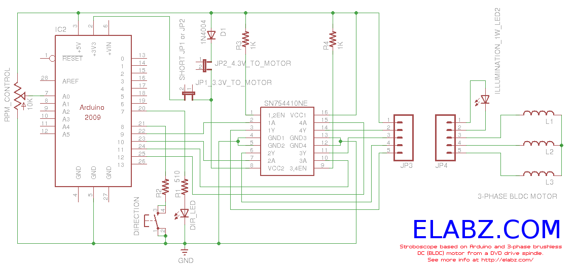
Constructing a stroboscope (zoetrope) using an Arduino and the spindle motor from a damaged Xbox 360 DVD drive. Includes zoetrope animations, Arduino code, and circuit schematic. The project involves utilizing an Arduino microcontroller to control the spindle motor extracted from...