
servo creating a switch using arduinos digital outputs
The circuit involves a basic connection configuration for a servo or motor control using an Arduino. The servo typically features two terminals: a positive (+) and a negative (-). The negative terminal is grounded, while the positive terminal connects to a digital output pin on the Arduino. This configuration is suitable for low-power applications but may not provide sufficient current to drive the servo effectively, leading to weak performance and the ability to stall the servo manually.
For optimal performance, the servo can be powered directly from a battery or the Arduino's 3.3V pin, which supplies a higher voltage and current, resulting in stronger operation. However, it is crucial to ensure that the power source matches the servo's specifications to prevent damage.
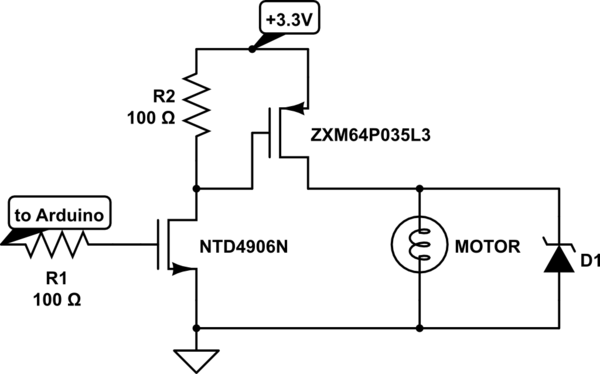
In more advanced applications, the use of a PMOS and NMOS transistor configuration allows for the control of higher voltage motors. The PMOS transistor acts as a switch that connects the motor to the power supply, while the NMOS transistor is used to control the gate of the PMOS. This configuration is beneficial when the motor voltage is higher than the control voltage from the Arduino (3.3V).
When selecting a PMOS transistor, it is essential to ensure that its gate-source voltage (VGS) is approximately 1/3 to 1/2 of the motor's operating voltage. Additionally, the PMOS should be rated to handle 30%-50% more current than the motor's maximum requirements to ensure reliable operation. The NMOS transistor must also be chosen carefully, ensuring that it can handle a voltage greater than that of the motor and that its VGS is less than 2V to ensure proper switching when driven by the Arduino.
This circuit design provides flexibility and enhances the performance of servo or motor applications, allowing for the control of motors with varying voltage requirements while maintaining safe operational parameters.Charge a simple servo that only has + and - pins. Usually I would connect it`s - pin to the ground and + pin to the digital output from Arduino. This works, but the servo turns weakly and can be stopped by hand. If i connect the servo directly to the battery or to 3. 3 pin from the Arduino it turns strongly and i cannot stop it. Pleas e add a datasheet or at least a picture of your servo. Edit your question, hit Ctrl-M and add a circuit diagram of how you are connecting things together. jippie May 12 `13 at 8:54 I don`t think you`re using the word "servo" correctly, What is sounds like you have is a motor or some sort of actuator. Connor Wolf May 12 `13 at 10:54 @jippie i added a link. And thank you for the warning, but I`m sure the servo will not get burnt, it can handle takes much more power that what arduino can give.
himura May 12 `13 at 16:12 The nice thing about this circuit is that you can drive higher voltage motors with it too. The PMOS is the ZXM part. If you want to get another PMOS make sure it`s VGS is about 1/3 to 1/2 of your motor voltage (in this case 3.
3V) and that it can handle 30%-50% more current than your motor needs. The NMOS is used to drive the PMOS since your motor voltage might be higher than 3. 3V - for some other use case. The only thing when selecting the NMOS is making sure it is rated for higher than your motor voltage and that it`s VGS is less than 2V (since you are driving it from a 3. 3V Arduino). 🔗 External reference
Related Circuits
Dimmer Switch - Dimmer Switch Working, Installation, Circuits and Explanation. A dimmer switch is a device that allows for the adjustment of the brightness of a light fixture. It operates by varying the voltage and current supplied to the light...
This circuit enables the remote switching of appliances via telephone lines. It allows for the control of appliances from any distance, surpassing the limitations of infrared and radio remote controls. The design accommodates up to nine appliances, corresponding to...
This digital volume control has no pot to wear out and introduces almost no noise in the circuit. Instead, the volume is controlled by pressing UP and DOWN buttons. This simple circuit would be a great touch to any...
The above shows a home-built digital clock that utilizes Nixie tubes for display. Unlike most contemporary Nixie clocks, this design does not employ transistors or integrated circuits for driving the tubes. Instead, the driving logic is constructed using neon...

The microprocessor-controlled oscillator has a frequency range of 8159 to 1, covering from 2 Hz to 20 kHz. An exponential, current output integrated circuit digital-to-analog converter (DAC) functions as a programmable current source, alternately charging and discharging a capacitor...

This circuit provides either latched switching or timed switching. U1A and U1B provide audio amplification from the microphone. U2 is a retriggerable monostable multivibrator. S1A and S1B select either U3, a flip-flop, or U2. R13 and R14 allow a...
Warning: include(partials/cookie-banner.php): Failed to open stream: Permission denied in /var/www/html/nextgr/view-circuit.php on line 713
Warning: include(): Failed opening 'partials/cookie-banner.php' for inclusion (include_path='.:/usr/share/php') in /var/www/html/nextgr/view-circuit.php on line 713