
Arduino UNO Tutorial Rotary Encoder

The rotary encoder circuit consists of two outputs, A and B, connected to digital input pins on a microcontroller. The microcontroller is programmed to monitor these pins at a specified frequency, which is critical for accurately detecting changes in the encoder's position. The use of a timer interrupt allows the microcontroller to perform other tasks while still effectively sampling the encoder outputs.
In the setup phase, the microcontroller initializes the necessary pins, designating one as an output for the LED and the others as inputs for the encoder signals. The main loop continuously checks the elapsed time against the defined interval. If the time threshold is met, the current state of the encoder pins is read. The logic implemented checks for changes in the A pulse and evaluates the state of the B pulse to determine the direction of rotation. The brightness of the LED is adjusted according to the direction of the encoder's turn, ensuring that the brightness value remains within the valid range (0-255).
This approach allows for smooth and responsive control of the LED brightness based on the rotary encoder's position, demonstrating the practical application of rotary encoders in electronic control systems. The code can be easily modified for additional functionalities or to adapt to different applications involving rotary encoders.With a rotary encoder we have two square wave outputs (A and B) which are 90 degrees out of phase with each other. The number of pulses or steps generated per complete turn varies. The Sparkfun Rotary Encoder has 12 steps but others may have more or less. The diagram below shows how the phases A and B relate to each other when the encoder is turned clockwise or counter clockwise. Every time the A signal pulse goes from positive to zero, we read the value of the B pulse. We see that when the encoder is turned clockwise the B pulse is always positive. When the encoder is turned counter-clockwise the B pulse is negative. By testing both outputs with a microcontroller we can determine the direction of turn and by counting the number of A pulses how far it has turned. Indeed, we could go one stage further and count the frequency of the pulses to determine how fast it is being turned.
We can see that the rotary encoder has a lot of advantages over a potentiometer. We will now use the rotary encoder in the simplest of applications, we will use it to control the brightness of an led by altering a pwm signal. We will use the easiest method to read the encoder, that is the use of a timer interrupt to check on the values.
We will use the sparkfun encoder as discussed above. The first thing is to determine how fast we need our timer to operate. If you imagine that at best we could turn the encoder through 180 degrees in 1/10th of a second, that would give us 6 pulses in 1/10th second or 60 pulse per second. In reality its never likely to be this fast. As we need to detect both high and low values this gives us a minimum frequency of 120Hz. Lets go for 200Hz just to be sure. (Note: as these units are mechanical switches, there is the possibility of switch bounce. Using a fairly low frequency allows us to effectively filter out any switch bounce) Each time our timer code triggers, we compare the value of our A pulse with its previous value.
If it has gone from positive to zero, we then check the value of the B pulse to see if it is positive or zero. Depending on the outcome we can increment of decrement a counter. We then use this to control the PWM value to increase or decrease the brightness of the LED And the source code for the sketch is shown below.
It builds on the previous tutorial where we used the millis() function to give us a timing interval. We use the same idea here but use 5ms as the elapsed time check (5ms = 200Hz). Hopefully, the code should be easy enough to understand and easily modifyable to put the Rotary Encoder to other uses. /* *RotaryEncoderExample *UsetheSparkfunRotaryEncodertovarybrightnessofLED * *Sampletheencoderat200Hzusingthemillis()function */ int brightness = 120; // how bright the LED is, start at half brightness int fadeAmount = 10; // how many points to fade the LED by unsigned long currentTime; unsigned long loopTime; constint pin_A = 12; // pin 12 constint pin_B = 11; // pin 11 unsigned char encoder_A; unsigned char encoder_B; unsigned char encoder_A_prev=0; void setup() { // declare pin 9 to be an output: pinMode(9, OUTPUT); pinMode(pin_A, INPUT); pinMode(pin_B, INPUT); currentTime=millis(); loopTime=currentTime; } void loop() { // get the current elapsed time currentTime=millis(); if(currentTime >= (loopTime + 5){ // 5ms since last check of encoder = 200Hz encoder_A=digitalRead(pin_A); // Read encoder pins encoder_B=digitalRead(pin_B); if(!encoder_A) && (encoder_A_prev){ // A has gone from high to low if(encoder_B) { // B is high so clockwise // increase the brightness, dont go over 255 if(brightness + fadeAmount <= 255) brightness += fadeAmount; } else { // B is low so counter-clockwise // decrease the brightness, dont go below 0 if(brightness - fadeAmount >= 0) brightness -= fadeAmount; } } encoder_A_prev=encoder_A;// Store value of A for next time // set the brightness of pin 9: analogWrite(9, brightness); loopTime=currentTime;// Update
🔗 External reference
Related Circuits
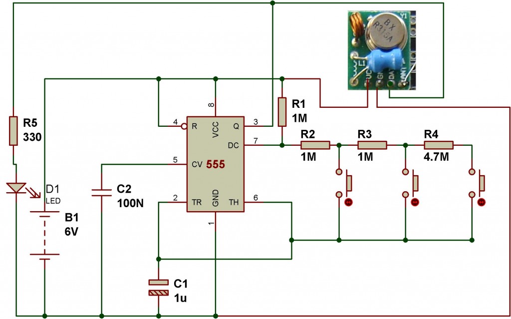
This wireless transmitter and receiver pair operates at 315 MHz. They can easily fit into a breadboard and work well with microcontrollers to create a simple wireless data link. As these are only transmitters, they will only facilitate one-way...
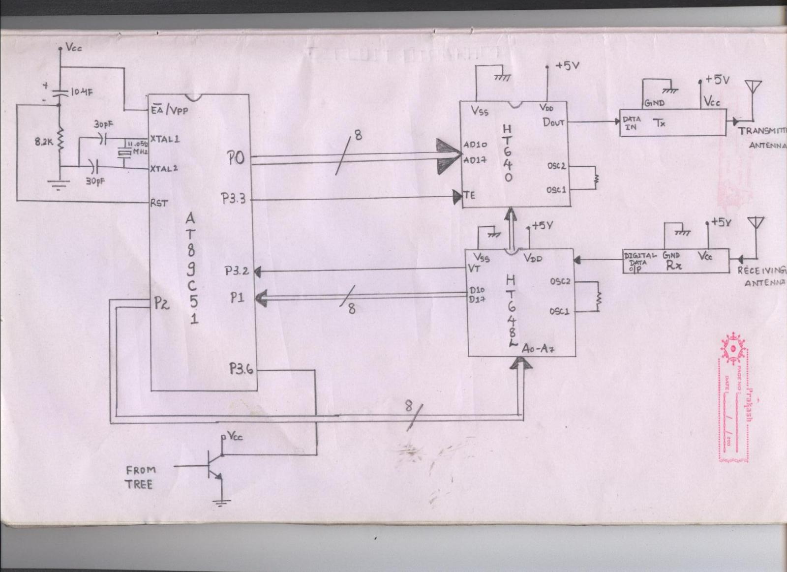
The issue arises when connecting the 8051 microcontroller to the HT640 encoder; the data transmitted is not received by the receiver. However, when the 8051 connections are removed, the transmission functions correctly. This indicates that manual RF communication works...
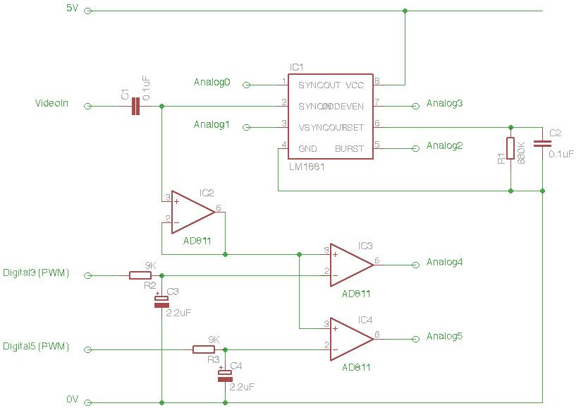
The Arduino Eye Shield is a circuit board that can be plugged on top of the Arduino, enabling it to interpret analog video (PAL or NTSC) from a camera or other source. This provides the Arduino with visual capabilities,...
A challenge encountered when beginning to work with Arduino was determining how to create circuit diagrams for projects. There are numerous software options available for drawing schematic diagrams, some of which are free while others require payment, each presenting...
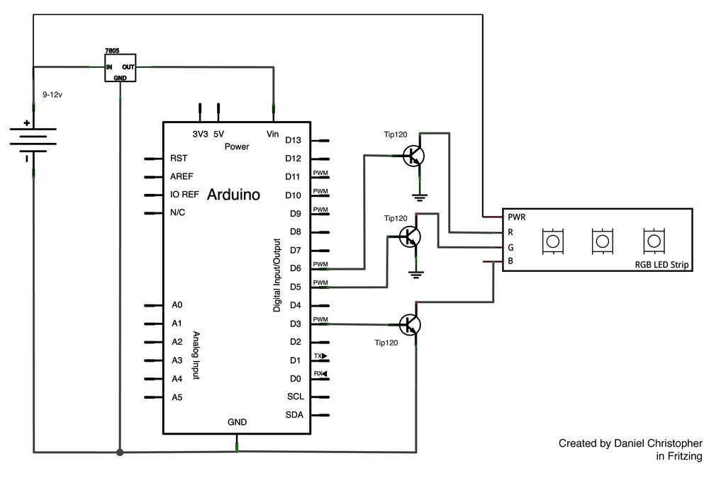
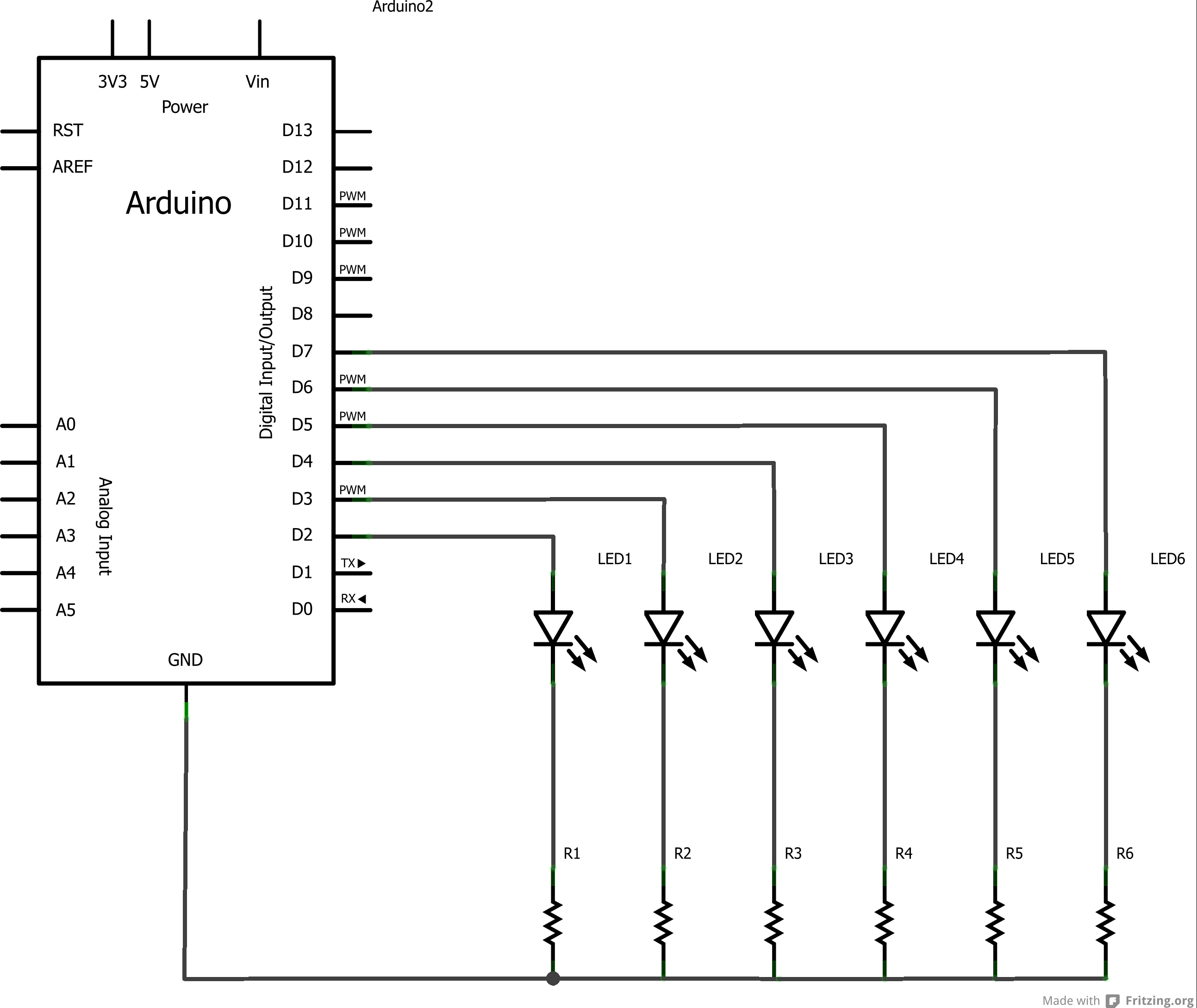
This document outlines the assembly of a circuit designed to pulse width modulate (PWM) a high-power RGB LED strip and program an Arduino to cycle through various colors. The high-power range is specified as 9-12 volts. The procedure includes...
Hartley Oscillator tutorial and the theory behind the design of the Hartley Oscillator, which uses an LC oscillator tank circuit to generate sine waves. The Hartley oscillator is a type of electronic oscillator that generates sine waves using an inductor-capacitor...