
how to use rf module with arduino

The wireless transmitter and receiver pair operating at 315 MHz is designed for compact integration into projects using microcontrollers, such as Arduino. The modules are particularly suited for applications requiring simple one-way communication. When implementing these modules, it is essential to recognize that they do not have unique identifiers, making them susceptible to noise from other devices operating on similar frequencies. This necessitates the implementation of a noise filtering mechanism to ensure reliable communication between the transmitter and receiver.
For effective operation, it is advisable to utilize two pairs of modules operating on different frequencies if bidirectional communication is required. This setup allows for distinct communication channels, reducing the risk of interference. The modules can be easily integrated into a breadboard, facilitating rapid prototyping and testing in various electronic projects.
The example provided in the documentation illustrates a basic setup using two Arduino boards. The transmitter is connected to Pin 12, and the receiver is connected to Pin 11. This configuration allows for straightforward programming and testing of the wireless communication link. The example code serves as a foundational reference, enabling users to expand upon it for more complex applications.
The versatility of these modules extends to a wide range of applications, including but not limited to remote control systems for vehicles, home automation, security systems, and various consumer electronics. The ability to control devices wirelessly enhances convenience and functionality, making these modules valuable components in modern electronic design. Users are encouraged to explore additional resources and example codes to optimize their wireless communication systems and ensure robust performance in their specific applications.This wireless transmitter and receiver pair operate at 315Mhz. They can easily fit into a breadboard and work well with microcontrollers to create a very simple wireless data link. Since these are only transmitters, they will only work communicating data one-way, you would need two pairs (of different frequencies) to act as a transmitt
er/receiver pair. Note:These modules are indiscriminate and will receive a fair amount of noise. Both the transmitter and receiver work at common frequencies and don`t have IDs. Therefore, a method of filtering this noise and pairing transmitter and receiver will be necessary. The example code below shows such an example for basic operation. Please refer to the example code and links below for ways to accomplish a robust wireless data link. Remote control switch, receiver module, motorcycles, automobile anti-theft products, home security products, electric doors, shutter doors, windows, remote control socket, remote control LED, remote audio remote control electric doors, garage door remote control, remote control retractable doors, remote volume gate, pan doors, remote control door opener, door closing device control system, remote control curtains, alarm host, alarm, remote control motorcycle remote control electric cars, remote control MP3. In this example, receiver and transmitter modules are connected separately to two Arduino boards. The transmitter data pin is connected to Pin 12 of Arduino and the receiver data pin is connected to Pin 11 of Arduino.
🔗 External reference
Related Circuits
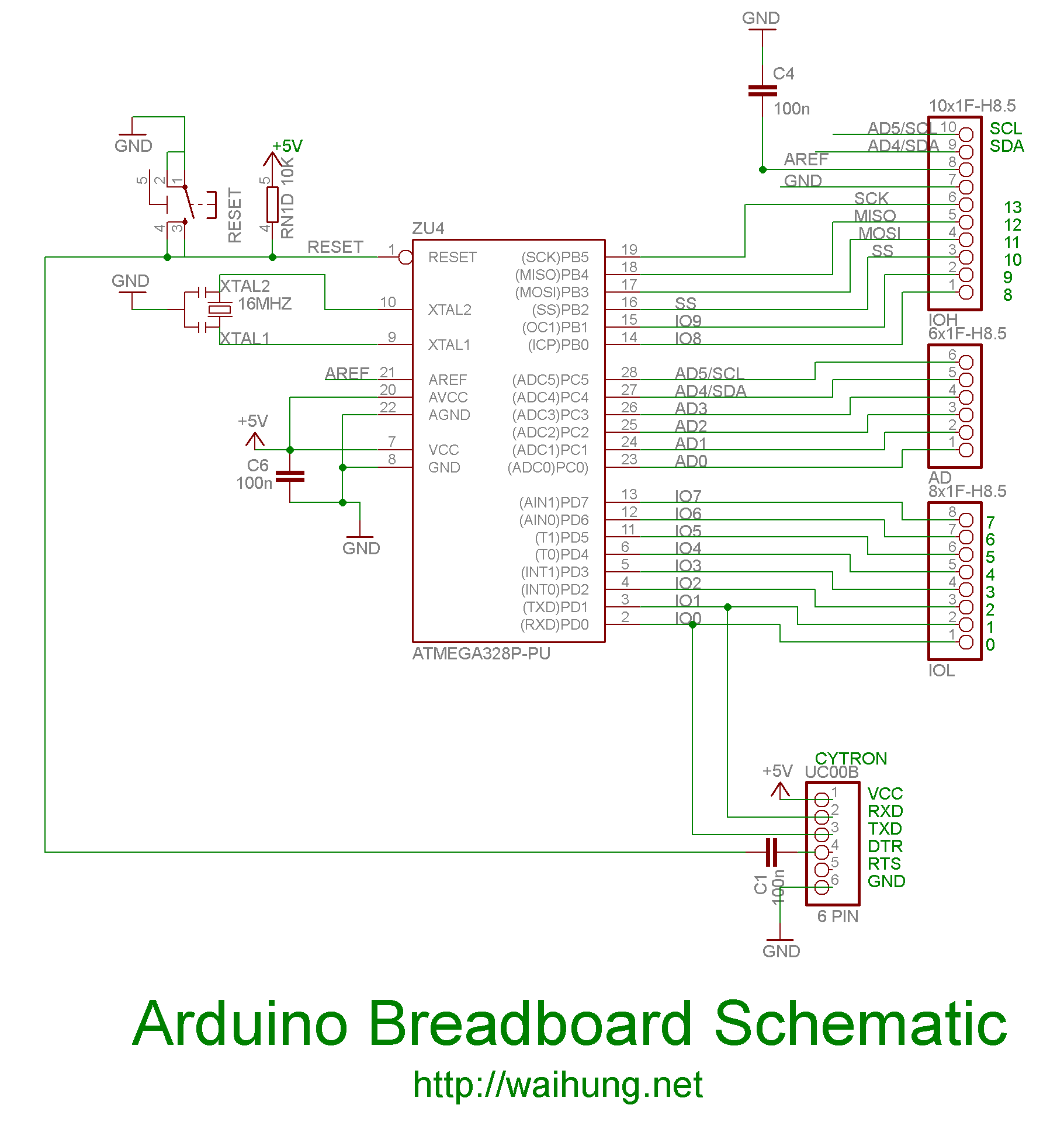
On the Uno boards, there is an integrated circuit (IC) that functions as a USB to serial converter, enabling programming and communication with the Arduino from a computer. This IC is a surface-mounted device (SMD). The R3 version utilizes...
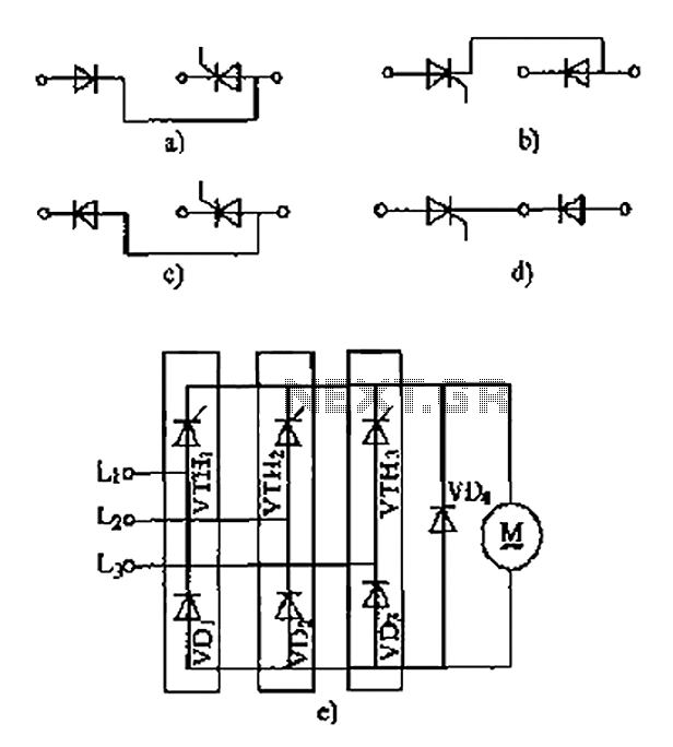
The thyristor linking arm rectifier module is a three-phase half-controlled bridge rectifier circuit. The thyristor-rectifier module linking arm consists of a thyristor and a rectifier diode connected in series or parallel, designed to fulfill specific requirements in power circuits....
This circuit is designed to provide alerts after a predetermined time interval. It is ideal for tabletop games that necessitate a fixed duration for answering questions or moving pieces. In this context, it serves as a contemporary alternative to...
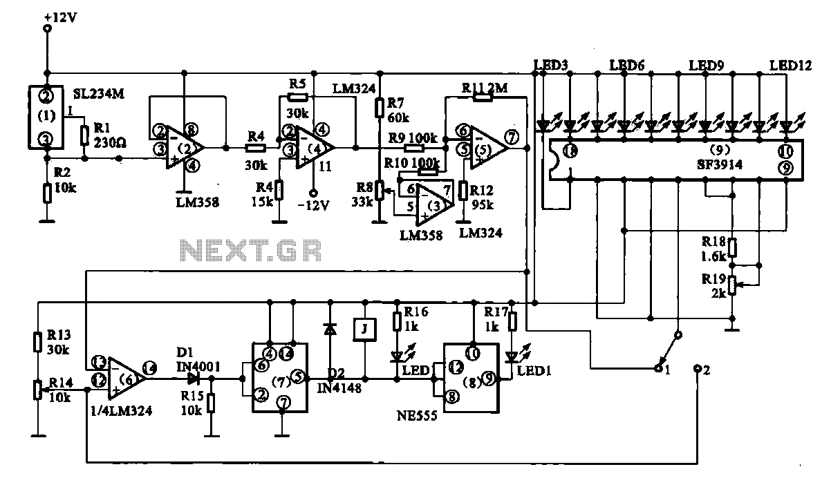
Vegetable greenhouse temperature detection control circuit. The greenhouse temperature detection control circuit is primarily composed of a temperature sensor SL234M, operational amplifiers LM324 and LM358, a dual time base circuit NE555, a relay, and a display driver circuit. The...
Capacitive sensors are utilized in various devices, ranging from consumer electronics to industrial and process control systems. Touch buttons are increasingly integrated into lamps and dimmers, while motion detectors can sense minute changes in deflection. Hygrometers measure humidity levels,...
In battery-powered applications such as cell phones, PDAs, and digital cameras, an integrated DC-DC converter circuit solution provides multiple advantages regarding cost, size, and design complexity. A significant challenge in achieving a fully integrated solution is designing the frequency...