
Arduino Vocal Effects Box Schematic

The audio output circuit typically involves several key components that work together to process and deliver sound signals. The primary elements include an audio source, an amplifier, and the output transducer, such as a speaker or headphone jack.
The audio source could be a microcontroller, a digital signal processor, or any device capable of generating audio signals. This source feeds the audio signal into an amplifier, which increases the signal's power to drive the output transducer effectively. The amplifier may be a class A, B, or D type, depending on the power efficiency and fidelity required for the application.
In the schematic, the audio output circuit may also feature capacitors and resistors for filtering and impedance matching. Capacitors are often used to block DC components while allowing AC audio signals to pass through, ensuring that only the intended audio frequencies are amplified. Resistors can help set the gain of the amplifier and provide stability to the circuit.
Moreover, the output stage may include protection circuits to prevent damage from overcurrent or voltage spikes, ensuring reliable operation. This can involve the use of diodes or fuses that safeguard the circuit.
Overall, the design of the audio output circuit is crucial for achieving high-quality sound reproduction, making it a fundamental aspect of audio electronics projects.I`ve broken the schematic into three parts so it is easier to understand. The first schematic shows the audio out circuit. This project outputs audio.. 🔗 External reference
Related Circuits
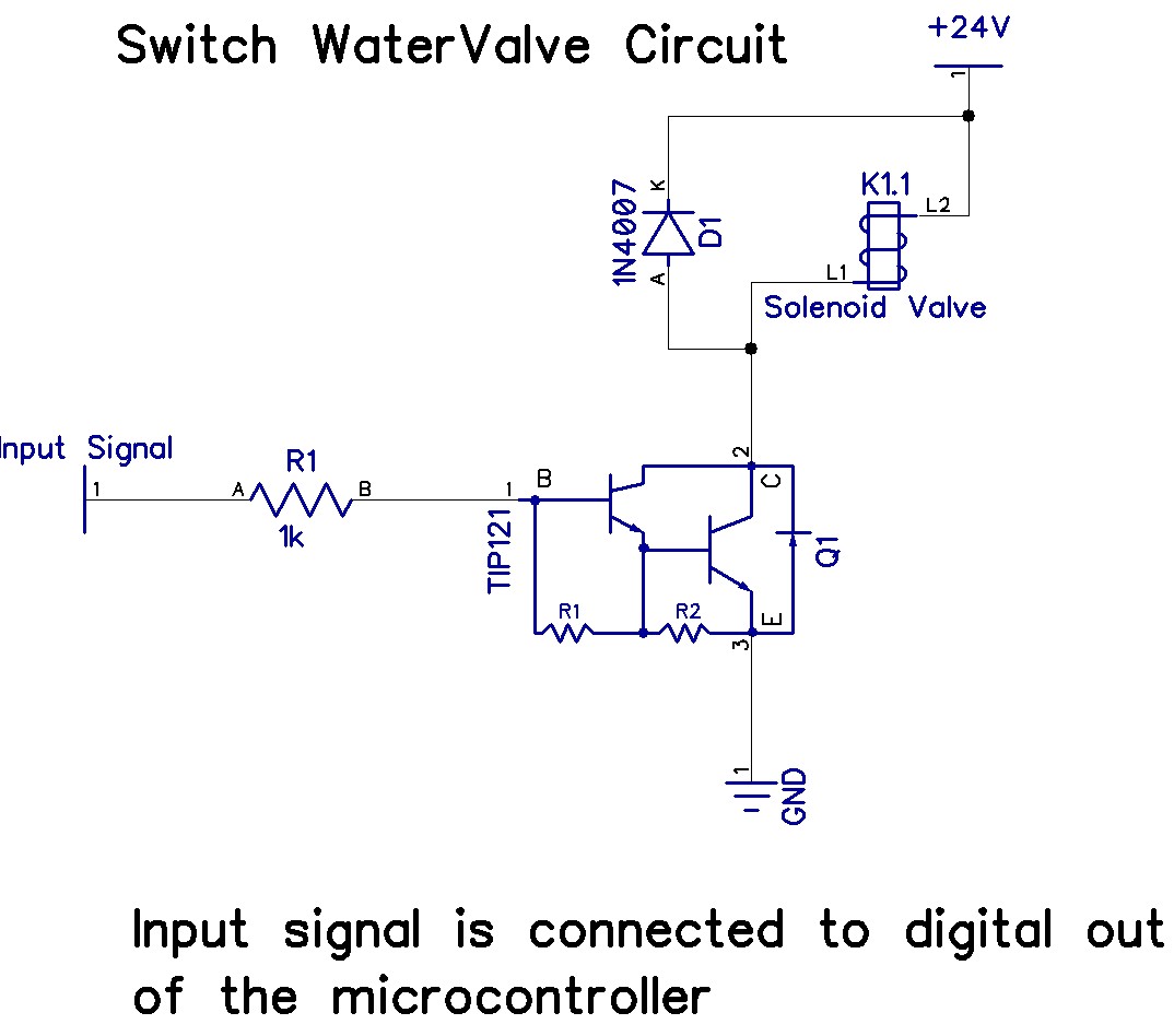
The Arduino Uno has adequate memory and ports, but efficient programming is necessary to store settings in memory. The Mega version offers increased memory and ports. The Shako valve operates on 24 volts DC; however, 12 volts is preferred...

The circuit employs two Light Dependent Resistors (LDRs) arranged in series with a separation of approximately half a meter. This configuration allows each LDR to detect the presence of a person entering or exiting the room. The processed outputs...

It has been determined that the Hijack method for obtaining serial data from the Mindflex to the iPhone will likely not be utilized. This decision is primarily based on the availability of most components needed to construct a similar...

The circuit is designed to stabilize the brightness of lamp L using a thyristor-based AC automatic voltage regulator. The thyristor T5 is connected diagonally across the bridge circuit. The trigger pulses are generated by components VT1, VT2, and VT3,...
This page is provided to the domain owner free by Sedo's Domain Parking. Disclaimer: The domain owner and Sedo maintain no relationship with third-party advertisers. References to any specific service or trademark are not controlled by Sedo or the...
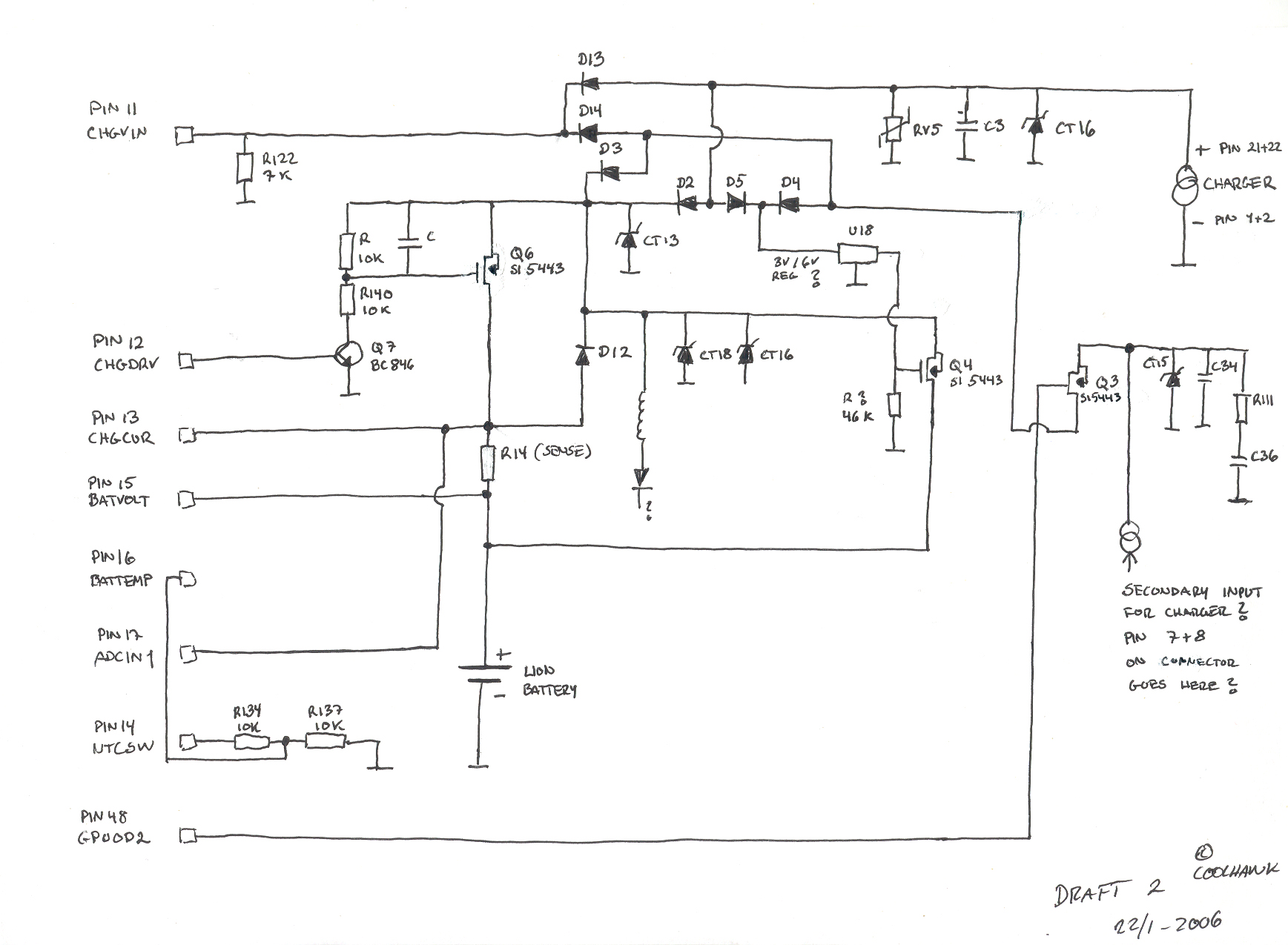
This is a basic hand-drawn schematic version 2. It will be transferred to Protel later when time permits. However, it provides a useful overview of the circuit, which can be charged from two different sources: USB or a standard...