
Lamp automatic exchange regulator circuit schematic
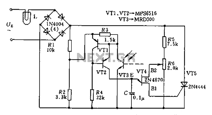
The circuit utilizes a thyristor (T5) as the primary control element to regulate the AC voltage supplied to lamp L. The configuration involves a bridge rectifier, which converts the AC input into a pulsating DC signal. The thyristor is triggered by a control mechanism that includes phototransistors (VT1, VT2, VT3) that detect the light intensity and adjust the conduction angle of the thyristor accordingly. This is achieved through a feedback loop that monitors the brightness of the lamp and adjusts the trigger pulses based on the variations in the power supply voltage.
The phototransistors serve a dual purpose; they act as sensors that respond to the light output of the lamp and as variable resistors that modulate the control voltage supplied to the thyristor. When the lamp's brightness diminishes due to a drop in supply voltage, the phototransistors increase their resistance, which in turn modifies the phase of the trigger pulse to the thyristor, allowing it to conduct for a longer duration. Conversely, if the brightness increases, the resistance decreases, leading to a shorter conduction time for the thyristor.
This feedback mechanism ensures that the lamp's brightness remains stable despite fluctuations in the input voltage, providing a consistent lighting experience. The design is particularly useful in applications where lamp brightness needs to be maintained at a specific level, such as in projectors or decorative lighting systems. The implementation of a thyristor-based regulator enhances the efficiency of the circuit by reducing power losses typically associated with resistive dimming methods. Circuit in order to stabilize the lamp brightness L, using thyristor AC automatic voltage regulator circuit. For this reason access thyristor T5 on a diagonal line from the exc hange of the bridge. Its trigger pulse VT1, VT2 and VT3 photosensitive tripolar equivalent resistance role played by the single crystal tube. When the projector lamp light because the power supply voltage changes, the change in resistance of the phototransistor, single-junction transistor control voltage phase also changed, so that the trigger pulse thyristor phase shift, increase or decrease the thyristor conduction time, L on the approximation of the voltage remains constant, the brightness of the lamp is also kept approximately constant, so that the light stability.
Related Circuits
This circuit is a high input voltage regulator that generates a voltage of 5V. In this circuit, the input voltage for the LM340 must remain within the limits specified in the datasheet. Operating the device above the absolute maximum...

This circuit is a module for a diesel and horn train system. It is constructed using a 555 timer IC and several operational amplifiers (op-amps). The circuit serves as a complete system for the horn function. The main power...
The diac is a common component used to trigger triacs. The construction of a diac is similar to that with a transistor, but with both junctions doped to similar levels so that the two junctions' reverse breakdown characteristics are...
Driving the highway with your high-beam headlights can really increase your visibility, but can be a blinding hazard for other drivers. This simple circuit can be wired into your headlight switch to provide automatic switching between high and low...
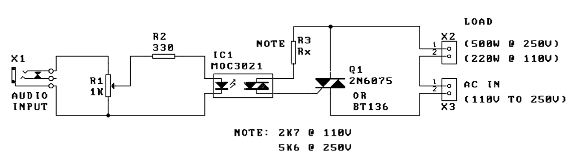
A music-to-light modulator is a circuit which controls the intensity of one or more lights in response to an audio input. The problem in older circuits is that there was a direct electrical connection between the lights using mains...
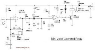
This circuit diagram represents a voice-operated relay. It functions similarly to a sound-activated switch circuit, which activates or deactivates the switch based on sound input. The output switch of this circuit operates through a relay. The voice-operated relay circuit typically...