
Armstrong Oscillator

The Armstrong oscillator is a notable example of a feedback oscillator that utilizes the principles of inductive coupling and resonant circuits to achieve stable oscillation characteristics. The design's reliance on an LC tank circuit, which consists of an inductor and a variable capacitor, allows for frequency tuning and stability. The mutual inductive coupling between the tickler coil and the tank circuit is crucial for the oscillator's regenerative feedback mechanism, which enhances the output signal's amplitude while maintaining the desired frequency.
In practical applications, the Armstrong oscillator finds utility in various RF and communication systems. Its ability to produce a stable sine-wave output makes it suitable for use in local oscillators within superheterodyne receivers, where it can mix with incoming RF signals to produce intermediate frequencies. Additionally, it serves as a reliable source in signal generators used for testing and calibration purposes in electronic laboratories.
The design of the Armstrong oscillator can be further optimized by selecting high-quality components that minimize losses and improve overall circuit performance. For example, using low-resistance inductors and high-capacitance capacitors can enhance the efficiency of the oscillator. Additionally, careful consideration of the transistor characteristics and biasing conditions is essential to ensure linear operation and avoid distortion in the output waveform.
Overall, the Armstrong oscillator's straightforward design and effective feedback mechanism make it a valuable circuit in the field of electronics, particularly in applications requiring stable RF signal generation.The ARMSTRONG OSCILLATOR is used to produce a sine-wave output of constant amplitude and of fairly constant frequency within the rf range. It is generally used as a local oscillator in receivers, as a source in signal generators, and as a radio-frequency oscillator in the medium- and high-frequency range.
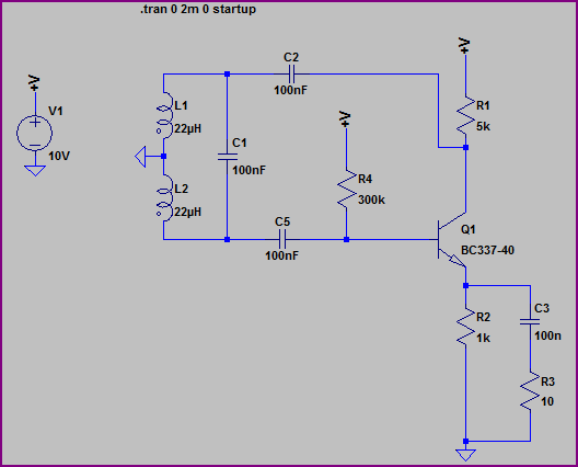
The identifying characteristics of the Arm strong oscillator are that (1) it uses an LC tuned circuit to establish the frequency of oscillation, (2) feedback is accomplished by mutual inductive coupling between the tickler coil and the LC tuned circuit, and (3) it uses a class C amplifier with self-bias. Its frequency is fairly stable, and the output amplitude is relatively constant. Views (A), (B), and (C) shown in the figure below can be used to build the basic Armstrong oscillator.
View (A) shows a conventional amplifier. R2 provides the forward bias for Q1, C2 is a coupling capacitor, and L1 and R1 form the collector load impedance. This is a common-emitter configuration which provides the 180-degree phase shift between the base and collector.
View (B) shows the frequency-determining device composed of inductor L2 and capacitor C1. C1 is a variable tuning capacitor which is used to adjust the resonant frequency to the desired value. View (C) is the feedback network which uses L1 (the collector load) as the primary and L2 as the secondary winding of a coupling transformer to provide a 180-degree phase shift.
Variable resistor R1 controls the amount of current through L1. When R1 is adjusted for maximum resistance, most of the current flows through L1. The transformer now couples a maximum signal which represents a large feedback amplitude into the tank circuit (L2, C1). If R1 is adjusted for a smaller resistance, less current flows through L1, and less energy is coupled to the tank circuit; therefore, feedback amplitude decreases.
R1 is normally adjusted so that the L1 current is adequate to sustain tank oscillations. View (D) shows the complete oscillator circuit. Connecting the feedback network through coupling capacitor C2 to the base of Q1 forms a "closed loop" for feedback (shown by the solid arrows). Let`s verify that the feedback is regenerative. Assume a positive signal on the base of Q1. The transistor conducts heavily when forward biased. This current flow through L1 and R1 causes the voltage across L1 to increase. The voltage increase is inductively coupled to L2 and inverted. This action ensures that the voltage is positive at the base end of L2 and C1 and in phase with the base voltage.
The positive signal is now coupled through C2 to the base of Q1. The regenerative feedback offsets the damping in the frequency-determining network and has sufficient amplitude to provide unity circuit gain. The circuit in view (D) has all three requirements for an oscillator: (1) amplification, (2) a frequency- determining device, and (3) regenerative feedback.
The oscillator in this schematic drawing is a tuned- base oscillator, because the fdd is in the base circuit. If the fdd were in the collector circuit, it would be a tuned-collector oscillator. The circuit in view (D) is basically an Armstrong oscillator. Refer to th figure again, view (D), for the following discussion of the circuit operation of the Armstrong oscillator.
When VCC is applied to the circuit. a small amount of base current flows through R2 which sets the forward bias on Q1. This forward bias causes collector current to flow from ground through Q1, R1, and L1 to +VCC. The current through L1 develops a magnetic field which induces a voltage into the tank circuit. The voltage is positive at the top of L2 and C1. At this time, two actions occur. First, resonant tank capacitor C1 charges to this voltage; the tank circuit now has stored energy. Second, coupling capacitor C2 couples the positive signal to the base of Q1. With a positive signal on its base, Q1 conducts harder. With Q1 conducting harde 🔗 External reference
Related Circuits
The RF engineer sometimes needs an instrument that can reliably and quickly test a low-frequency quartz crystal unit. Finding such equipment can be challenging, and engineers often refer to electronic circuit handbooks for schematics that can perform this task....
The circuit was designed to generate an oscillator that operates at low frequencies, intended for use in electronic music production, experimentation, and testing. The low-frequency oscillator (LFO) circuit typically consists of several key components, including resistors, capacitors, and an operational...
A Hartley Oscillator circuit can be constructed using a pair of series-connected coils. Two 22mH fixed inductors were utilized on a breadboard along with other necessary components. Testing the transistor amplifier independently indicated proper functionality; however, there is no...

The term VCXO refers to a Voltage Controlled Crystal Oscillator. The frequency of this oscillator can be fine-tuned by varying the control voltage. VCXO clock generators are utilized in a range of applications, including digital telecommunications. VCXO circuits are essential...
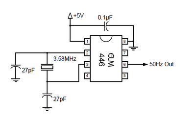
The ELM446 is an 8-pin digital divider integrated circuit that generates both 50Hz and 1Hz outputs from a common 3.58MHz NTSC colorburst crystal. The designer needs to supply only the crystal and two suitable loading capacitors, along with a...
Generating variable audio frequencies with crystal precision is challenging due to the scarcity of low-frequency quartz crystals, which typically produce a single frequency. While minor adjustments to the frequency of a crystal oscillator can be made using a trimmer...