
Can a Hartley Oscillator be built using Fixed Inductors
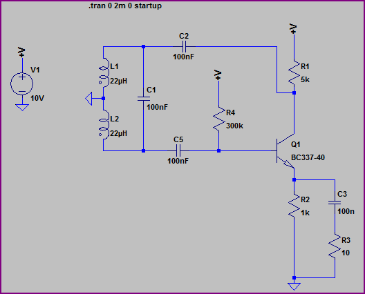
The Hartley oscillator is a type of LC oscillator that generates sine wave signals and is characterized by its use of inductors and capacitors to create an oscillation frequency determined by the values of these components. In a typical Hartley oscillator circuit, two inductors (L1 and L2) are connected in series, and a capacitor (C) is connected across the combination to form a resonant tank circuit. The feedback for the oscillator is provided through a tap on one of the inductors, which ensures that the circuit can sustain oscillations.
In this context, the use of two 22mH fixed inductors is appropriate, provided they are connected correctly to form the necessary feedback loop. It is essential to ensure that the inductors are not too tightly coupled, as excessive mutual inductance can lead to instability or prevent oscillation altogether. Therefore, the distance and orientation between the inductors should be optimized to achieve the desired coupling without impeding the oscillation process.
The transistor amplifier plays a critical role in the oscillator's operation, as it provides the necessary gain to sustain oscillations. If the transistor is functioning correctly when tested independently, the issue may lie in the feedback configuration or the values of the passive components. It is important to verify the connections and ensure that the feedback path from the inductors to the transistor is correctly implemented.
To achieve oscillation, the total phase shift around the loop must be 360 degrees, which can be affected by the values of the inductors and capacitor. Adjusting the capacitor’s value can help in tuning the frequency of oscillation. If no oscillation is observed when attempting to change the frequency, it may indicate that the circuit is not properly configured or that the components are not suitable for the desired frequency range.
In summary, the Hartley oscillator circuit requires careful consideration of component values, layout, and feedback configuration to ensure successful oscillation. If oscillation remains elusive, further investigation into component interactions and circuit design may be necessary to identify and resolve the underlying issues.An Hartley Oscillator circuit can be made from a pair of series connected coils. I had a couple of 22mH fixed inductors, which I hooked up on a breadboard with the other needed pieces. When I test the transistor amplifier independently, it seems to be working. However, there is no sign of oscillation in this circuit. So my ignorant question is, can I use the fixed inductors indicated I saw mention of the notion of `mutual inductance`, and I`m not sure you can get such with these discrete components. However, I clearly still have a long way to go, as when we attempted to change the frequency of the circuit we were mimicking, we got zero oscillation.
And the original Hartley circuit remains stubborn. 🔗 External reference
Related Circuits
Here is a simple triangle/squarewave generator using a common 1458 dual op-amp that can be used from very low frequencies to about 10 Khz. The time interval for one half cycle is about R*C and the outputs will supply...
The VNGBOX microcontroller must generate a precise, high-resolution, and low-noise DC control voltage to accurately steer the reference oscillator phase. Any noise on this signal can introduce noise to the reference, and any non-linearity, particularly unexpected steps in the...
Construct a personal arc welder. Many individuals have eagerly anticipated the release of these comprehensive plans, which are available for purchase and download in a 4.6MB PDF file for a nominal fee. The arc welder is a vital tool in...
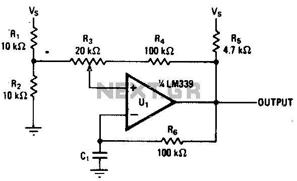
Varying the amount of hysteresis in this comparator circuit allows for smooth adjustment of output frequencies within the range of 740 Hz to 2 kHz. The hysteresis level, in combination with the time constant formed by resistor R6 and...
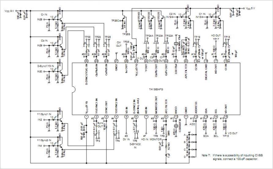
The TA2003PG and TA2003FG are integrated circuits designed for AM/FM radio applications. These ICs facilitate AM/FM radio functionality, including FM front-end and AM/FM intermediate frequency processing. When combined with the TA7368P mono power amplifier IC, a comprehensive AM/FM radio...
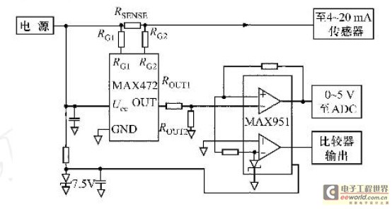
Field bus technology and intelligent instrument technology are currently two of the most rapidly evolving technologies in automation and control. In the realm of field bus technology, the CAN bus has established itself as a relatively fast communication standard...
Warning: include(partials/cookie-banner.php): Failed to open stream: Permission denied in /var/www/html/nextgr/view-circuit.php on line 713
Warning: include(): Failed opening 'partials/cookie-banner.php' for inclusion (include_path='.:/usr/share/php') in /var/www/html/nextgr/view-circuit.php on line 713