
Crystal audio oscillator circuit
Parts and materials:
- B1 - Battery, 5 Volt
- C1 - Capacitor, 50 pF, Rotary
- C2 - Capacitor, 50 pF, Rotary
- C3, C4 - Capacitor, 0.1 µF, Disc
- C5 - Capacitor, 0.05 µF, Disc
- IC1 - Integrated Circuit, TTL, SN7400, Quad NAND
- IC2 - Integrated Circuit, TTL, SN7404, Hex Inverter
- R1, R2 - Resistor, 220 Ω, 5%, 1/4W, CC
- R3, R4 - Resistor, 120 Ω, 5%, 1/4W, CC
- R5 - Resistor, 1 kΩ, 5%, 1/4W, CC
The circuit operates by utilizing two oscillators that generate distinct frequencies, which can be mixed to produce a composite audio output. The choice of TTL components ensures compatibility and reliability, while the use of inexpensive color television crystals provides an accessible means to achieve the desired frequency generation. The design allows for easy adjustments and modifications, making it suitable for various audio applications.Generating variable audio frequencies with crystal precision is not often done because it isn`t easy to make. Low frequency quartz crystals are difficult to find, and each would only provide a singular frequency.
Some small tweaking of the crystal oscillator`s frequency with a trimmer capacitor is common, but the variation is almost insignificant. Most, but real expensive oscillator designs usually produce low audio frequency waves with time proven, dependable, stable, adjustable Twin-T and Wien-bridge sine-wave oscillators. Many of the better ones of these use large size inductors and good quality large, high-grade capacitors.
If square waves, triangle waves or pulses are needed then the sine wave is chopped up, processed and amplified as necessary. For less precise requirements some home made 555 circuit will usually do even if most of those - because of the uncertainty of the IC`s trigger point - has noticeably high jitter.
This circuit is a working example that combining two frequencies produces a new useable audio product. Block diagram of this AF oscillator is depicted on Figure 1. This unique oscillator circuit uses two regular, TTL ICs and two of the most often used, low cost, color TV crystals in an unusual way.
Using one quad NAND IC for both oscillators worked reliably but it had a tendency of the oscillators of locking together. That problem arises because both of the oscillators were sharing the same silicon chip, and thus they had too much coupling and influence on each other.
The easiest way to prevent the lock-up is to make one oscillator out of one IC - the 7400 quad NAND gate package. Use the 7404 hex inverter for the other oscillator. The nominal quartz frequency for a color television crystal is 3, 579, 545 kHz and one is used for each oscillator.
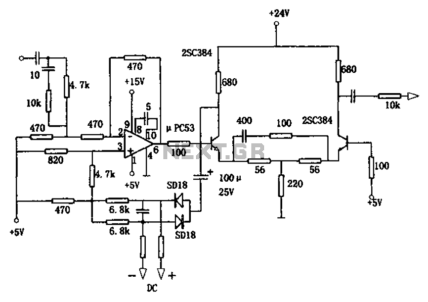
As seen on the schematics - Figure 2, the crystal oscillator frequencies are adjusted with a small 50pF rotary capacitor. The oscillation is a high frequency that is adjustable by a small amount. With the circuit as shown, with a five-volt power supply, the audio output frequency range is 10 Hz to a little over 2 kHz.
The gates used are all belong to the first generation TTL group. It is very beneficial if the inside circuit is known to save many hours spent on discovery work. The inside circuit topology of the IC - Figure 3 - and the parts values are important to design a stable oscillator configuration. Almost any currently available logic family is useable in this circuit with some minor modification of some component values.
The LS version of these gates, or CMOS or other parts is also useable without much difficulty. All components used are easy to find and tolerances are not critical. These early TTL components were chosen, because they have good information on them. Figure 4, has all mixer waveforms before the low-pass filter. The filter section used here to attenuate the unwanted higher frequency harmonics. Parts and materials: B1 - Battery, 5 Volt C1 - Capacitor, 50 pF, Rotary C2 - Capacitor, 50 pF, Rotary C3, C4 - Capacitor 0. 1 uF, Disc C5 - Capacitor 0. 05 uF, Disc IC1 - Integrated Circuit, TTL, SN7400, Quad NAND IC2 - Integrated Circuit, TTL, SN7404, Hex Inverter R1, R2 - Resistor Resistor, 220, 5%, 1/4W, CC R3, R4 - Resistor Resistor, 120, 5%, 1/4W, CC R5 - Resistor Resistor, 1k, 5%, 1/4W, CC
🔗 External reference
Related Circuits

This circuit utilizes a 4049 integrated circuit (IC) to control a 2N2222 switching transistor. The transistor, in turn, drives a piezo transducer known as crystal 1. The circuit design begins with the 4049 IC, which is a hex inverter capable...
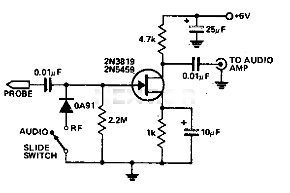
This economical signal tracer is useful for servicing and alignment work in receivers and low power transmitters. When switched to RF, the modulation on any signal is detected by the diode and amplified by the FET. A twin-core shielded...
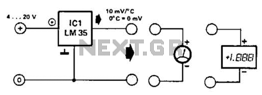
An effective temperature sensor circuit is designed to receive power from a 4-to-20 mA loop without impacting the loop current. The temperature sensor integrated circuit (IC) used is the AD590F, which operates with a supply voltage ranging from 4...
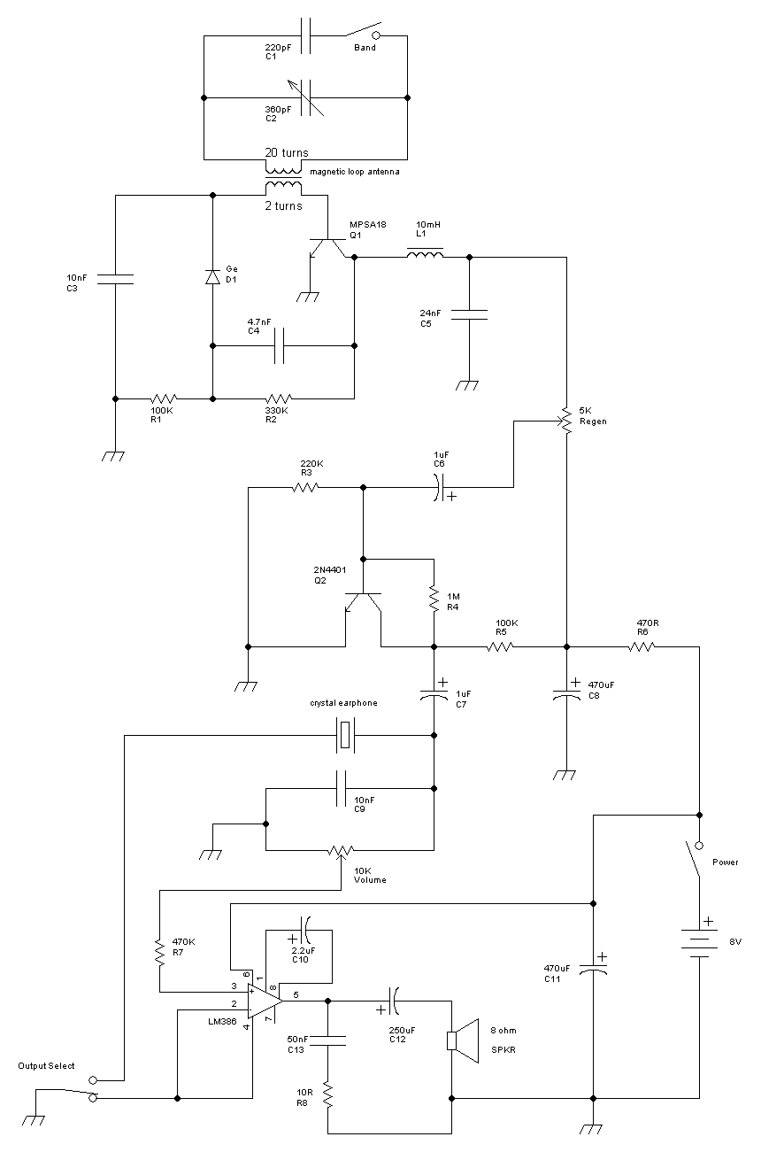
This receiver is a modification of Charles Wenzel's Two Transistor Reflex Radio. Instead of a ferrite AM loopstick antenna, a magnetic loop antenna is used, and an LM386 amplifier stage has been added to drive an 8-ohm speaker. A...
The circuit is designed for a broadband linear detection application with a bandwidth of 10 MHz. It serves as a millivoltmeter measuring instrument suitable for frequencies exceeding 10 MHz. The circuit features a linear detector utilizing operational amplifiers, specifically...
A potentiometer regulates the firing point of the triac. Capacitor C4 is charged through resistors R3, R4, P1, and R5. After a specific duration, determined by the potentiometer setting, the charge in C4 becomes sufficient for the diac D...