
Signal Meter circuit
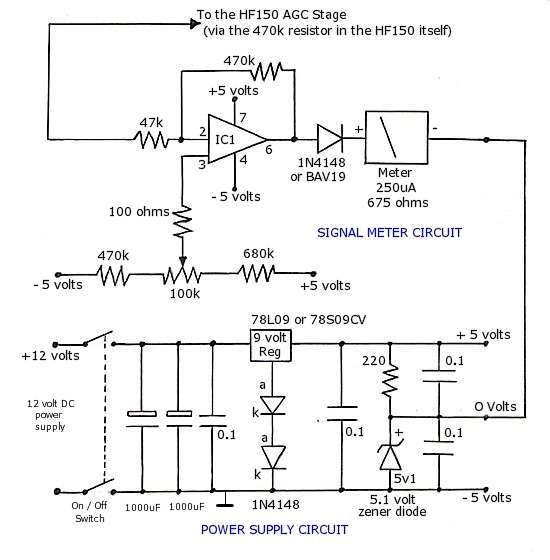
The TL061 operational amplifier is a JFET-input op-amp known for its low noise and high-speed performance, making it suitable for audio and signal processing applications. The LF351, also a JFET-input op-amp, provides similar characteristics and can be used interchangeably with the TL061 due to its pin compatibility. The LM741, a general-purpose op-amp, is widely used in various applications, though it may not perform as well in high-frequency scenarios compared to the TL061 and LF351.
The circuit design incorporates essential components such as the power supply, op-amps, and signal input/output connections, ensuring proper functionality of the signal meter. The use of 8-pin D.I.L. sockets for the op-amps facilitates maintenance and upgrades, allowing for easy replacement without soldering. The dual 12V power input sockets enhance versatility by enabling daisy-chaining with additional equipment, providing a scalable solution for signal measurement.
The signal meter's scale is designed to reflect the non-linear response of radio signals, emphasizing the importance of the lower signal strengths (S1 to S9) in assessing reception quality. This design choice aligns with practical radio operation, where minor variations at lower signal levels significantly impact the perceived quality of the audio output. The calibration of S9 at 50 µV is a widely accepted standard, providing a reference point for users to gauge signal strength effectively.
Furthermore, the ability to modify the HF-150 to connect an external signal meter highlights the adaptability of the design, allowing users to enhance their radio's capabilities. Identifying the AGC line is crucial for this modification, as it directly influences the signal processing within the receiver. This adaptability ensures that the circuit remains relevant for various radio models, offering a practical solution for signal strength measurement across different platforms.THE OP-AMP: The Op-Amp used for the signal meter circuit is a TL061. An LF351 works just as well, however and has the same pin layout. If you have a TL062 or similar the differing pin-outs are shown below so that you can design your circuit board successfully. The diagram above shows the pin layout of the TL061 and some alternative op-amps that ca n also be used in the signal meter circuit described on this page. The LF351 op-amp also works in this design and is pin compatible with theTL061. Another pin compatible op-amp that is usually easy to obtain, or that may be knocking about in the `junk box` is the very common LM741. I have not tried an LM741 in this circuit, but I can see no reason why it would not work. Rather than solder any op-amp directly to the circuit board, I would strongly recommend that you use 8 Pin D.
I. L. sockets so that the I. C. can be easily inserted and removed. The 2 power sockets mounted to the right of the back panel are the 12v power input sockets (2 are fitted to allow `daisy-chaining` of the power to another unit) NB - the 0 Volts connection between the negative side of the meter movement and the 0 Volts output from the power regulator circuit should not be connected to the metal case or ground. The small socket on the left is the 2. 5mm Jack that allows connection of the signal meter to the radio. You can just see the single grey wire that connects the 2. 5mm socket to the circuit board. The top half of the board accommodates the signal meter components ( Note how relatively small changes in voltage at the lower end of the scale ( in the S1 to S8 range) produce quite noticable swings in the readings, while really quite large changes in signal voltage at the higher end of the scale ( S9 to S+50 ) produce quite small variations in read-out.
This non-linear effect is quite intentional: Increases in signal strength from S1 to S9 will produce dramatic improvements in the received signal to noise (S/N) radio while above around the S9+10dB signal level the receiver is approacing the best acheivable S/N ratio and further large increases in signal strength will make less if any improvement to the audible S/N ratio, so the S Meter does not really need to reflect these changes in such minute detail. Although there is no set standard for S-Meter calibration, it seems widely accepted that the S9 reading is calibrated for a signal input of 50 µV.
(Although some manufacturers may calibrate S9 at 100 µV). Additionally the gradation between each S unit is generally accepted as 6dB. i. e. S2 is 6dB greater than S1 and S9 is 12dB greater than S7 etc. As can be seen in the table above 6dB represents a doubling of the voltage received by the radio. (It may also be worth pointing out that for a receiver to receive double the voltage from a transmitting station, the transmitting station would have to increase its effective radiated power level by four times. ) In real life the signal meter on many radios may not be accurately calibrated to 50 µV at S9 and each individual S unit may not, indeed, accuratelt represent 6dB intervals.
Some meters may represent the interval as 5dB or 4dB. However an S Meter`s visual representation of relative signal strengths will still be very useful in judging differences between signal strengths of different stations and particularly useful with antenna experiments. A minor modification to the HF-150 is required to enable an external signal meter to be connected. The AGC (automatic gain control) line on the receiver`s printed circuit board needs to be identified and an explanation was proveded by Lowe for the HF-150, but a similar connection could feasably be made to the AGC line of any other receiver.
This may be marked as a pin on an IC or next to a transistor or other component. You may be able to find the circuit diagram for your radio in the handbook or be able to abtain one from the manufacturer or from a search of the 🔗 External reference
Related Circuits

A GdS cell serves as one leg of a bridge circuit. Potentiometer R6 in another leg establishes the trip point. Potentiometer R5 allows for hysteresis adjustment to prevent chattering or hunting of the relay. The light level must increase...
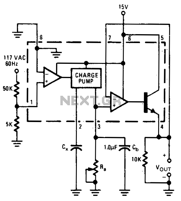
The output voltage is proportional to the capacitance connected to pin 2 of the charge pump. The meter operates over a capacitance range of 0.1 to 0 µF with a set resistance of 111 kΩ. Within this capacitance range,...

A simple touch dimmer circuit diagram using the TT6061 IC, which is a touch control integrated circuit used for light dimmer circuits and lamp dimmer circuits. The touch dimmer circuit utilizing the TT6061 IC is designed to provide a user-friendly...
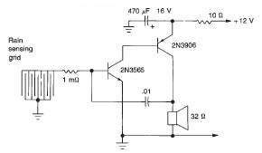
This rain detector electronic circuit project is a simple alarm circuit that activates an audio warning when liquid is detected on the sense pad. The circuit diagram is based on two transistors. When the sense pad conducts, transistors Tr1...
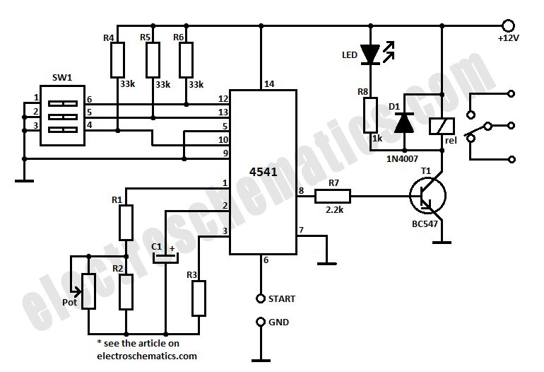
To initiate the timing process, there are two options available: either connect the START point to ground (GND), in which case the timer activates when connected to the voltage supply, or employ a switch to start the timer. The timing...
This is a simple RF bug detector designed to identify spy bugs, capable of operating up to 2 GHz. Below are some essential components required for this circuit. The RF bug detector circuit functions by utilizing radio frequency signals...
Warning: include(partials/cookie-banner.php): Failed to open stream: Permission denied in /var/www/html/nextgr/view-circuit.php on line 713
Warning: include(): Failed opening 'partials/cookie-banner.php' for inclusion (include_path='.:/usr/share/php') in /var/www/html/nextgr/view-circuit.php on line 713