
tone control circuit using tda1524a
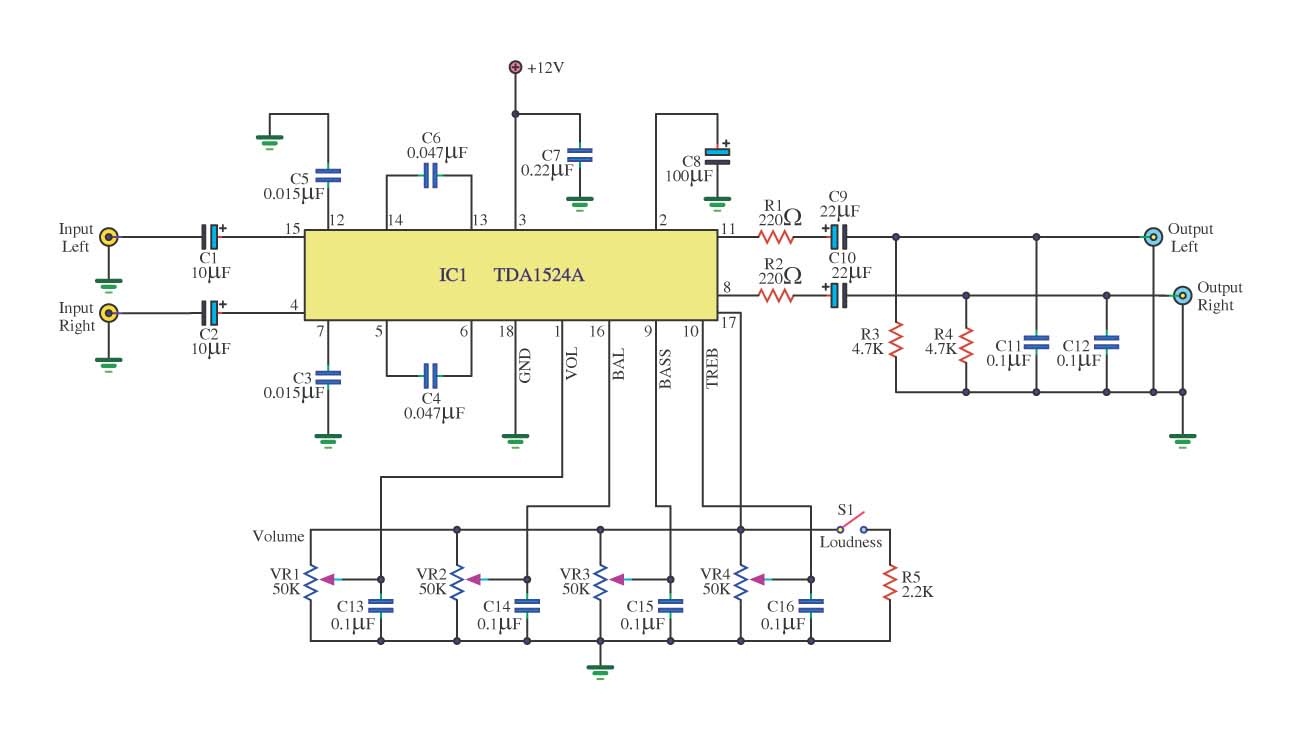
The audio signal from the sound source is fed into pin 15 of the IC. The input signal is coupled through capacitors C1 and C2 for the left and right channels, respectively. The IC amplifies these signals, with capacitors C6 and C4 playing a role in controlling the sound frequency. The switch S1 allows users to choose the tone control settings. Capacitors C5 and C3, along with variable resistors VR1 to VR4, are used to adjust volume, balance, treble, and bass settings.
After amplification and frequency adjustment, the signal is sent to pins 8 and 11 of the audio IC. Resistors R1 and R2 reduce the right channel signal level, while capacitors C9 and C10 couple the signals. Resistors R3 and R4 eliminate DC components, and capacitors C11 and C12 filter out high frequencies above 70 kHz. The processed audio signal is then outputted, producing clear sound.
The TDA1524A tone control circuit design is particularly beneficial for audio applications requiring precise sound adjustments. The use of capacitors for coupling and filtering ensures that the audio output remains clean and free from unwanted noise. The low distortion rate enhances audio fidelity, making this circuit suitable for various audio systems. Additionally, the straightforward construction of the circuit allows for easy implementation in both educational projects and practical applications. The ability to adjust bass, treble, and balance allows users to customize their listening experience according to personal preferences or specific audio environments.This is an a simple Tone Control Circuit using TDA1524A. Is the heart pillar in the work that is IC chip diagram of Philip. You can use a tone control or a portion of the lower portion of fines sound, treble and balance to get all setly can be extended by a given signal power can reach up to 3 Vrms with 20 dB and rates expansion are guilty are cra zy just over 0. 014% with a frequency of 1 kHz and important. The circuit is not difficult to build a team and soon, then old suit of education or be used indoors or outdoors can apply the work should be done. Duty cycle starts from the input power supply built into the pin 3 is the positive voltage and negative voltage to pin 8, this circuit will only Class C and R of the devices to filter out frequencies in different areas.
Some may work then. When the signal from the sound source to pin 15 of IC1, the input signal is coupled through C1 and C2 signals from each channel. Left and right, then the IC signals are amplified with the C6 and C4 for controlling the frequency of the sound from the Department that the switch S1 is the option of using the tone control a region or sector will adjust the bass Cape C5 and C3 act as control VR1-VR4 frequency to adjust the volume, balance, treble and bass, respectively.
Then the signal was expanded and adjust the frequency, and sends the pin 8 and pin 11 of audio IC of each box R1 and R2 will serve to diminish the right signal And the signal coupling through C9 and C10, with R3 and R4 removing DC comes from the earth to the C11 and C12 will be to remove high frequencies from 70 kHz up. A land, and then sends the signal to the output signal and a voice came out clear. 🔗 External reference
Related Circuits
This circuit switches a printer's USB connection from a PC to a laptop. The objective was to create a solution that enables a laptop to use the printer intermittently while maintaining the printer's primary connection to the PC. Instead...
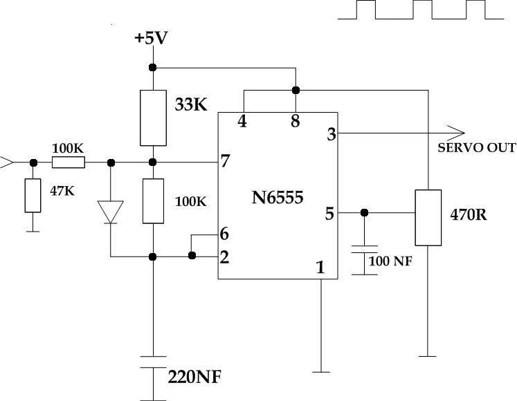
This circuit takes a standard 0-10V control voltage (for example, from an analog light control desk) and outputs a standard 1-2 ms control pulse for RC servo motors. The components used in this circuit include: - 2 x 100...
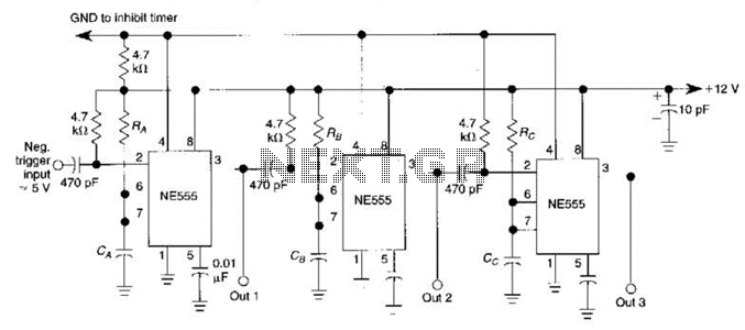
The circuit is designed around a 555 oscillator/timer, providing two distinct time periods. The longer time period can be adjusted between approximately 1 to 10 minutes, while the shorter time period is fixed at around three seconds. The operation...
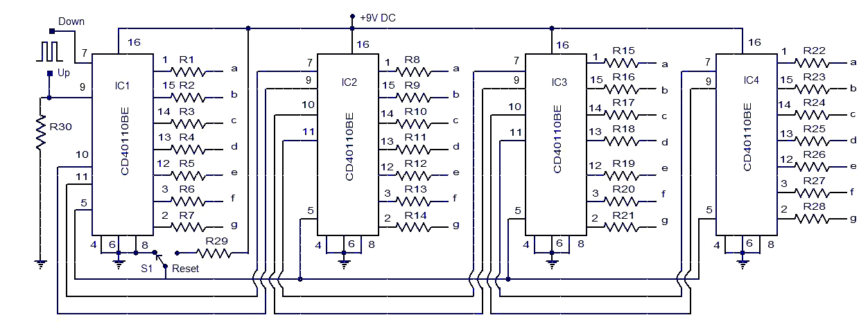
This circuit diagram illustrates a simple up/down counter suitable for various applications. It utilizes the CD40110BE IC, a CMOS decade up/down counter. Common cathode seven-segment displays are connected to the outputs of each IC. The display connected to IC1...
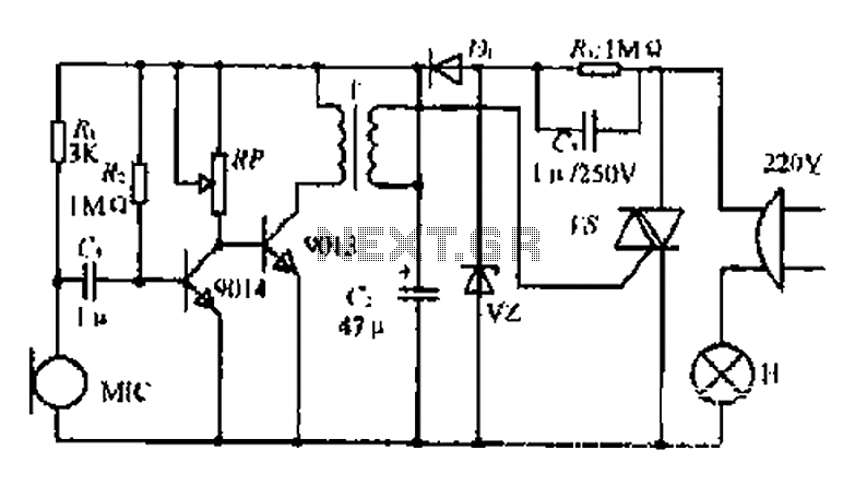
22W by Ct and R, RC Buck, rectified by n. c, filtering. vz 3V DC regulated output power, before U, V2 and MIC power supply. When the audio signal reaches the beam, the microphone MI converts acoustic energy into...
This is a circuit design for a temperature relay that can be used to signal a fire or monitor temperature set points. The adjustment of P1 is necessary to ensure that the base voltage of T1 is 0.5V lower...