
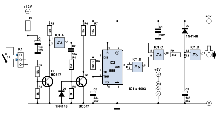
astable mode of 555 timer

The circuit in question is versatile, allowing for multiple configurations based on component values and connections. The primary components include resistors (R1, R2), a capacitor (C1), and an optional light-dependent resistor (LDR). The values of R1 and R2 determine the frequency of the oscillation, which is crucial for generating sound in the music generator mode. Adjusting these resistances can lead to different musical notes being produced.
When configured as an infrared transmitter, the circuit emits modulated infrared signals, which can be used to test IR sensors effectively. This application is particularly useful in various projects, such as remote controls or proximity detection systems. The infrared output can be tuned by changing the capacitor value, thus affecting the modulation frequency.
For the infrared-based object counter application, the removal of the LDR allows for a more straightforward design. By adding a series of switches and resistors, the circuit can be transformed into a simple organ, where each switch corresponds to a different note or sound. This modification enhances the educational value of the project, providing insights into sound synthesis and electronic circuit design.
Overall, the schematic serves as a foundation for experimentation and learning in electronics, showcasing the flexibility of basic components in creating diverse functionalities.The following schematic has been taken from buildcircuit. com. The following circuit can work as a music generator, Infrared transmitter and LED blinker depending upon the values of R1, R2 and C1. Making a minor modification in the previous circuit makes it work as an infrared transmitter. We can use this infrared transmitter for testing IR sensor circuit and making an infrared based object counter. You can modify the circuit in the following way. Simply remove the LDR and add series of switches and resistors to make a simple organ. Click here to read more about this project. 🔗 External reference
Related Circuits
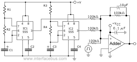
This circuit combines the outputs from two distinct 555 multivibrators using a summing operational amplifier (Op Amp). It serves to illustrate an alternative implementation of a 555 timer, with most background calculations addressed in other sections. The standard configuration...
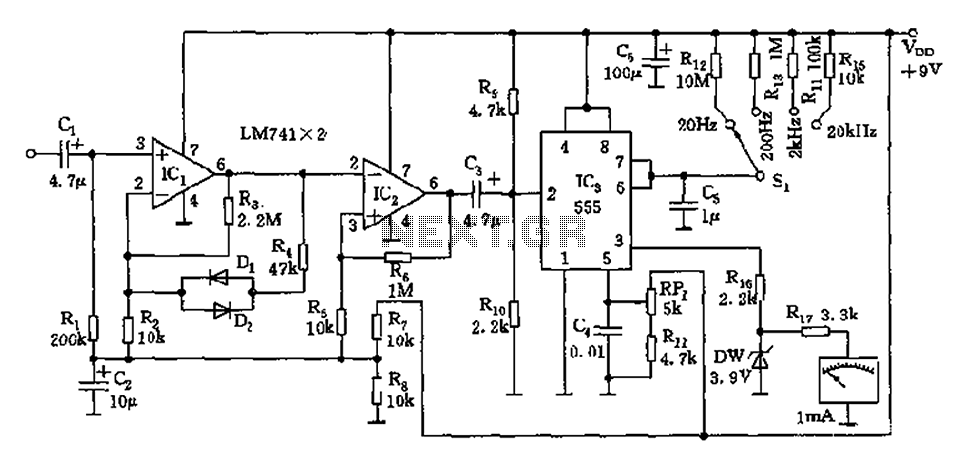
The circuit is a direct-reading frequency meter that utilizes an amplifier and a one-shot trigger circuit, along with table-top components. It is capable of directly detecting a 1mA signal at the read head, with a maximum signal frequency of...
A PIR sensor is triggered when using a timer to wait for 2 seconds after the sensor is activated. Without the timer, the sensor operates as intended. The PIR sensor is connected to an ATMega328p microcontroller, which has three...
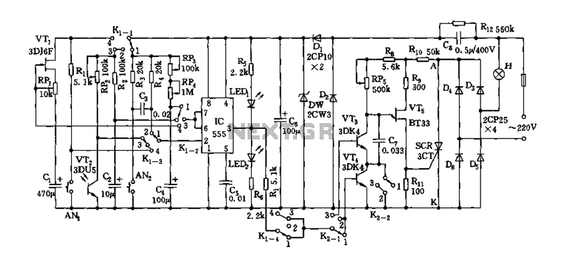
Depending on the external circuit connection, the 555 timer can be configured for various modes such as start delay, trigger delay, multi-harmonic oscillation, and other operational conditions. It functions as a versatile tester with the inclusion of some RC...
Anyone who has designed circuits using the 555 timer chip has, at some point, wished for the ability to program longer timing periods. Timing intervals exceeding a few minutes are challenging to achieve due to the significant impact of...
The circuit described here was designed as an addition to a remotely controlled garage door opener. The problem was that a brief burst of interference, arising from a thunderstorm or a mains spike, was enough to trigger the mechanism,...