
Astable Multivibrator Calculations

In the context of an astable multivibrator circuit, two transistors (Q1 and Q2) are configured to toggle between on and off states, creating a square wave output. The capacitors C1 and C2 play a critical role in determining the timing characteristics of the circuit. The time period for charging and discharging these capacitors is influenced by the resistance values and the capacitance, as described by the formula T1 = 0.693C(R2). The voltage across the capacitors is governed by the exponential charging and discharging behavior, represented by the equation V(t) = Vo e^(-t/RC), where Vo is the initial voltage across the capacitor, and V(t) is the voltage at time t.
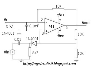
The feedback mechanism, where the base of Q1 is connected to the collector of Q2 and vice versa, ensures that the transistors switch states in a coordinated manner, allowing for stable oscillation. The voltage limiting observed in the circuit can be attributed to the interaction between the capacitors and the transistor base-emitter junctions, which have specific threshold voltages. The three equal resistors in the 555 timer configuration assist in establishing reference voltages for the comparators, thus contributing to the overall voltage limiting behavior.
The observed voltage of 3.7V across C2 when C1 is charged to 600mV indicates a transient condition in the circuit. This voltage level is a result of the capacitive coupling and the charge redistribution between the capacitors during operation. Understanding the precise relationship between the voltages and the timing components is essential for accurate predictions of circuit behavior. Further analysis and simulations may be required to derive a clear mathematical relationship for the maximum voltage across C2, particularly under varying conditions and component tolerances.for the time in which it gets charged to 0. 6V, the other capacitor has already charged a whole lot(a value which I can`t figure out because the setup does not work until i reach one of the two states-Q1 is on or Q2 is on) The only reason the equation Tl=0. 693C(R2) exists is because we assume that the capacitor starts at 1/3Vcc and goes up to 2 /3Vcc in time Tl using the capacitor discharge equation. But in the above astable multivibrator, there is no indication(that I can see at least) of voltage limiting. So in the equation V(t)=Voe(-t/RC), what is Vo and what is V(t) I was a student at ITT Tech nearly 12 years ago.
I had the basics back then. I went over some of the basics at TTC (my current school) but not into the basic-basics. I understand everything, but don`t remember all the math (I have my text books). Give me about an hour and I should be able to find those formulas (I`m cooking atm). Most of what I know I`ve scavenged from the internet. No formal electronics edu, just cheap 12th std physics. which is why I have no idea about the math (and very little about everything else for that matter) Grob`s Basic Electronics (they are up to 11th edition, I have 8th), Operational Amplifiers and Linear Integrated Circuits: Theory and Applications, Digital Systems: Principles and Applications (7th edition, don`t know what they are up to now) edit: DS: PaA is an experiment book fwiw. Looking again at the circuit diagram you provided. all I can assume is that as a whole they provide the voltage limiting. The base of Q1 is connected to the collector of Q2 with C2 in series, and Q2`s base is in series with the collector of Q1 with C1 in series.
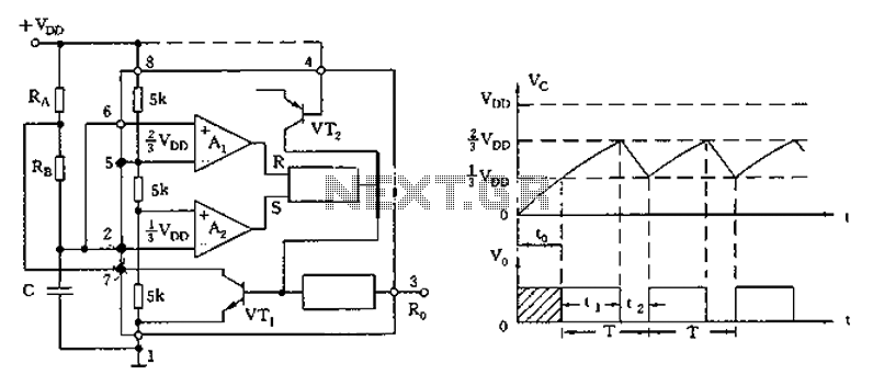
Perhaps that set up (seems like it provides feedback ) is what limits the voltage Though as I understand it, the three equal resistors in the 555 are what provide the voltage limiting for the comparators (sorry to go back to it again) in either astable or monostable. I can kind of understand why the upper limit voltage is 0. 6V (I checked it on a simulator circuit sim! - it does go to 600mV and then discharges), but that`s because the base of the transistors are triggered at that voltage.
Now when C1 is charged to 600mV, I found(on the simulator) that C2 has a voltage of 3. 7V(approx) across it. At this time, C1 discharges and C2 begins to be charged the other direction so it goes 3. 7V->0V->-600mV. I`m not sure where this maximum 3. 7V voltage came from. I can easily see that the cap will never charge up to Vcc because it will inevitably discharge earlier(because the other cap has to charge only to 600mV), that part is fine. But I can`t seem to find an equation or a definite relation for the maximum voltage on C. All the references start the explanation of the circuit from a state where Q1 is either just turned off or on.
But by this time, 3. 7V has already been generated across C2. 🔗 External reference
Related Circuits
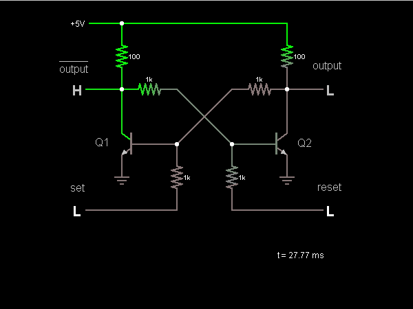
This circuit is a bistable multivibrator, commonly known as a flip-flop. Activating the "set" input located at the lower left corner will raise the output to a high state (5V). Conversely, engaging the "reset" input at the lower right...
Many friends have requested an automatic on/off LED circuit or an LED flashing circuit. This post presents an astable multivibrator circuit designed for LED flashing. It is a simple astable multivibrator circuit utilizing two LEDs (specifically red LEDs) and...
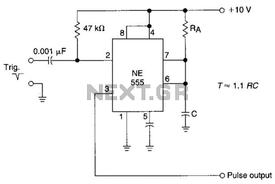
The time constant of RAXC determines the period of the monostable multivibrator. A negative pulse at pin 2 of the 555 starts the cycle. The monostable multivibrator is a circuit configuration that produces a single output pulse in response...
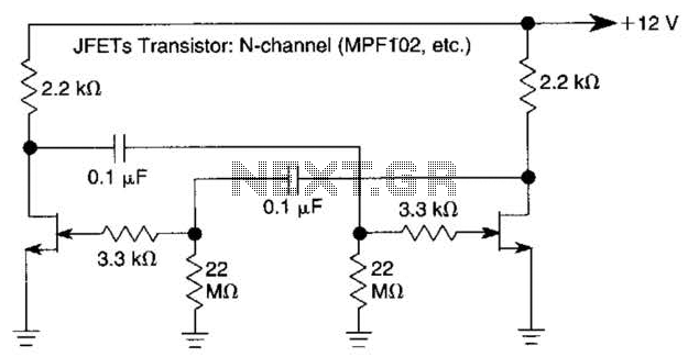
The use of JFETs allows for high resistance and long time constants in this very low frequency multivibrator. The values indicated are for operation at 0.15 Hz. In the context of electronic circuit design, a multivibrator is a circuit that...
The circuit remains in a stable state until a triggering signal is applied to its input. Upon receiving the triggering signal, the output transitions from a stable state to a quasi-stable state and returns after a specified time period,...
The circuit diagram illustrates the 555 timer (or 556 timer in half configuration) configured in astable multivibrator mode. It features three resistive and capacitive elements connected as shown. In one-shot mode, the trigger terminal (pin 2) is connected to...