
Astable Multivibrator Or Free-Running Square-Wave Oscillator Circuit
The circuit operates as a basic oscillator, generating a square wave output through the interaction of two NPN transistors. The fundamental principle behind this oscillator is feedback, where the output of one transistor is fed back into the base of the other, allowing for continuous oscillation.
In this configuration, the two transistors are arranged in a feedback loop. When one transistor turns on, it allows current to flow through its collector to emitter, which subsequently provides base current to the second transistor. This causes the second transistor to turn on, allowing current to flow through it and providing base current back to the first transistor. This rapid switching between the two transistors generates the square wave output.
The frequency of oscillation, approximately 300 Hz, can be adjusted by changing the values of the resistors and capacitors in the circuit. Typically, a resistor-capacitor (RC) network is used to set the time constant, which directly influences the frequency. For instance, increasing the capacitance or resistance will lower the frequency, while decreasing these values will raise the frequency.
Power supply considerations are also important; the circuit requires a DC voltage source suitable for the transistors being used. It is essential to ensure that the transistors are rated for the voltage and current levels present in the circuit to prevent damage.
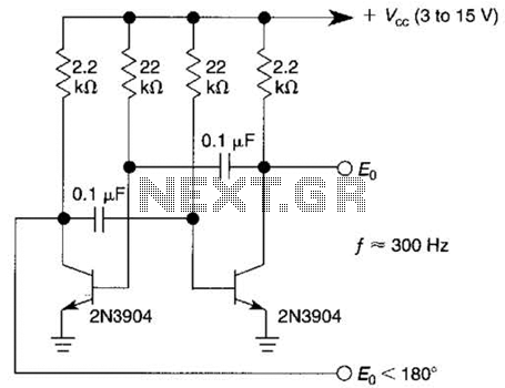
Overall, this circuit is a simple yet effective way to generate square wave signals, commonly used in applications such as clock pulses for digital circuits, tone generation, and signal modulation. Proper component selection and configuration are crucial for achieving the desired frequency and stability of the oscillator. This free-running square-wave oscillator uses two npn transistors. Output frequency is approximately 300 Hz with the values shown. 🔗 External reference
Related Circuits
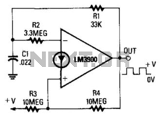
When the output is high, R3 and R4 are in parallel, and C1 charges through R1 until the current in R2 equals that at the non-inverting terminal. This action occurs when C1's voltage rises to 2/3 of the supply...
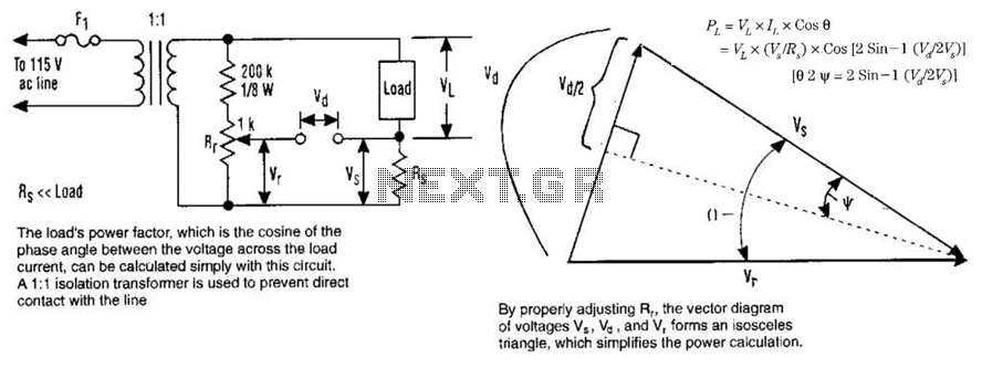
The load's power factor, defined as the cosine of the phase angle between the voltage across the load and the load current, can be calculated using this circuit. An isolation transformer with a 1:1 ratio is employed to prevent...

The TPS61200 specifications indicate that GND serves as the control/logic ground, while PGND is designated as the power ground. However, this distinction is not accurately represented in the symbols used in the diagram. There is also confusion regarding the...
The purpose of this circuit is to animate shop windows using a capacitive sensor positioned behind a postcard-like banner. The card is placed against the glass inside the shop window, allowing visitors to activate the relay by placing their...
A newcomer to the forum is seeking assistance with DIY electronic circuits and lacks a formal background in electrical engineering. The inquiry indicates a desire to learn and engage with the community on topics related to DIY electronic circuits. For...
The internal mute circuit and pre-set gain resistors provide a cost-effective design solution. Output power specifications at both 20V and 24V supplies, along with a low external component count, offer significant value to consumer electronic manufacturers for stereo TV...