
Atari joystick to PC joystick adapter
The interface circuit directly connects the joystick buttons to the corresponding PC joystick connector pins because they operate similarly in both joystick types. Since the PC requires different resistances for the X and Y inputs to determine the joystick position, the circuit converts the four switch inputs from the Atari stick connector to the different X and Y resistance values, which are outputted to the PC joystick port. The circuit provides the following resistance values from the nine different positions an Atari-style joystick can have: the resistance values are identical to those produced by PC gamepad controllers (like the Gravis Gamepad for PC) or what a normal PC analogue joystick outputs when it is in the center position or in any extreme position (fully moved to one of the eight main directions).
The different resistance values are generated using the following method (this example is for forward/back direction movement):
When the digital joystick is in the center position, the current flows through R3, D1, and the potentiometer. When the potentiometer is adjusted to the center position, the PC joystick interface sees approximately 50 kohm resistance. No current flows through T1. When the Forward switch is closed, the point between R3 and D1 is grounded. Now, the current can only flow to the PC joystick interface through the potentiometer, which provides a 100 kohm resistance. When the Forward switch is closed, current begins to flow from T1's emitter to the base and then through R2 to the forward switch. This base current causes T1 to conduct from emitter to collector, leading the PC joystick interface to perceive a very low resistance.
The Left/Right movement conversion operates in the same manner. The normal digital joystick button is connected to Button 1 input in the PC joystick interface, and one extra button in the digital joystick connector is wired to Button 2 in the PC joystick interface.
It is important to note that the transistors and diodes are essential for this circuit to function. The use of active circuit elements is necessary to convert an unmodified Atari joystick to a PC joystick port. While there are simpler circuits that utilize only a few resistors to adapt a joystick to a PC, these cannot be used with unmodified Atari joysticks as they require complete rewiring of the joystick internals, which is not always feasible as demonstrated in their circuit diagrams. The intention of this circuit is to be general and to avoid any modifications needed inside the joystick.ome games are easier to play with digital joystick instead of analogue type. Unfortunately PC has only analogue joystick connector, which makes it impossible to connect normal digital joystick to it. But with a little adapter circuit, it is possible to use Atari style digital joystick with IBM PC joystick interface.
The circuit adapts the joystick connectors and converts digital joystick movement signals to analogue signals. The circuit can be used with any PC game to replace the original analogue joystick. The circuit also simulates also Gravis Gamepad operations except the extra buttons. R1,R3,R4,R6 2.2 kohm R2,R5 100 kohm T1,R2 BC557 D1,D2 1N4148 P1,P2 100 kohm trimmer Generally the circuit is not very sensitive to the component differences on diodes and transistors. Generally almost any small signal transisotr with Hfe on range of 100-500 should do the job. For the diode you can use almost any common diode, like very popular 1N4001 rectifying diode. The circuit operation The interface circuit directly connects the joystick buttons to the corresponding PC joystick connector pins because they operate similarly in both joystick types.
Because PC need different resistances to X and Y inputs to know the joystick position, the circuit converter the four switch inputs form the Atari stick connector to the different X and Y resistance values which are the outputted to PC joystick port. The circuit gives the following resistance values from the 9 different positions an Atari-style joystick stick can have: The resistance values are exactly the same as what is given by PC gamepad controllers (like Gravis Gamepad for PC) or what normal PC analogue joystick give out when it is in center position or in any extreme position (fully moved to one of the eight main directions).
The different resistance values are generating using following method (this example is for forward/back direction movevement): When the digital joystick is in center position the current flows through R3, D1 and potentiometer. When potentiometer is tuned center position the PC joystick interface seen around 50 kohm resistance.
No current flows through T1. When the Forward switch is closed the point between R3 and D1 is grounded. Now the current can only go to PC joystick interface though the potentiometer, which give 100 kohm resistance. When Forward switch is closed then current starts to flow from T1 emitter to base and then through R2 to forward switch.
This base current causes that T1 starts to conduct from emitter to collector so the PC joystick interface sees very low resistance. Left/Right movement conversion works in exactly the same way. Normal digital joystick button is wired to Button 1 input in PC joystick interface and one extra button in digital joystick connector is wired to the Button 2 in PC joystick interface.
NOTE: The transistors and and diodes are absolutely necessary for this circuit to work. You can"t avoid using active circuit elements if you want to to convert and unmodified Atari joystick to PC josytick port. I know that there are some simple circuits which use only few resistor to adapt joystick to PC, but those can"t be used with unmodified Atari joysticks.
They require you to completely rewire internals of the joystick (which is not always possible as shown in their circuit diagrams). The intention of my circuit was to make the circuit general and avoid any changes needed inside the joystick.
🔗 External reference
Related Circuits
A low-cost DC adapter can be utilized to construct a stabilized and uninterruptible 9V power supply. For safety and cost-effectiveness, a simple unstabilized 12V DC adapter serves as the power source; a universal adapter set to 12V will also...
Whenever I'm in the car listening to my favourite CD, it always happens - my batteries go dead. To solve that problem, I built this extremely simple regulator circuit. It steps down the 12V from the lighter socket to...

This circuit is designed to measure the inductance of an inductor labeled LX. The output of the circuit generates a TTL square wave, with its frequency being directly related to the inductance being measured. The output from the inductance...
The joystick button inputs can be used as general purpose button or switch inputs, and can also be driven by logic level signals or by open collector or open drain logic outputs. If used with a signal direct from...
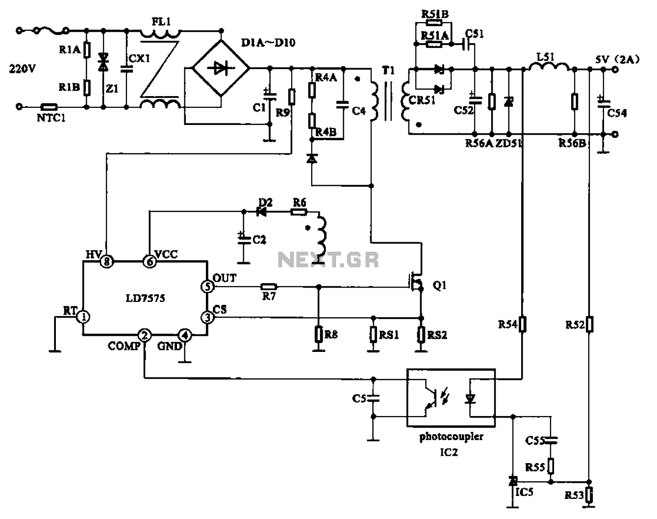
The AC adapter circuit is designed for portable digital products, converting low voltage DC into 220V AC. It features a circuit configuration for a switch power drill utilizing the oscillation IC LD7575 as a switch. This IC operates after...
This smartcard adapter follows exactly the specification ISO 7816. Also, the protocol is the "asynchronous half duplex T=0 protocol" with "active low reset" and "inverse convention" as defined in this standard. The following description may be used in order...