
inductance meter adapter circuit

The circuit operates by utilizing a Colpitts oscillator, which is a type of LC oscillator known for its stability and simplicity. The oscillator's design incorporates an inductor (LX) and capacitors (C1, C2, C3, C4) that form the resonant tank circuit. The frequency of oscillation (f) is calculated using the formula:
\[ f = \frac{1}{2\pi\sqrt{L \cdot C}} \]
where L is the inductance in henries and C is the total capacitance in farads. In this case, the total capacitance is the equivalent capacitance of the four capacitors, which can be calculated for series and parallel configurations.
The sine wave output from the oscillator is first amplified by a transistor (Q1), which increases the signal strength to ensure it can drive the next stage effectively. The rectification stage, consisting of a diode (D1) and a smoothing capacitor (C5), converts the AC sine wave into a pulsating DC signal. This rectified signal is then buffered by a second transistor (Q2) to provide a strong, clean signal suitable for the counter IC.
The 74LS393 counter IC is a dual 4-bit binary counter, and in this application, it is configured to divide the incoming frequency by 256. The division factor is crucial, as it allows for the conversion of high-frequency signals into a manageable range that can be easily read by the connected frequency meter. The output from pin 6 of the IC represents the divided frequency, which correlates to the inductance value being measured.
Overall, this circuit provides an effective method for measuring inductance through frequency analysis, leveraging the properties of oscillators, amplification, rectification, and digital counting. The design ensures accuracy and reliability in measuring inductance values across a range of inductor types.This is a design circuit for measure inductance of the inductor labeled LX which is the inductance to be measured. The o/p of the circuit is a TTL square wave whose frequency relates to the inductance being measured.
The inductance meter adapter output is connected to a frequency meter and the inductance is calculated from the frequency. This is t he figure of the circuit; The center operate of the circuit is the buffer colpitts oscillator(the first stage) which resonates with the unknown inductance to give a Sine wave of a particular frequency. The frequency of the sine wave is a function of the unknown inductance and the four 1000pF capacitors.
The output sine wave is amplified by the second transistor and is then rectified by the capacitor and diode combination that follows. The rectified sine wave now having only positive excursions is buffered by the third transistor and is then fed to the 74ls393.
Counter IC which is configured as a divide by 256 counter. The output of the IC pin 6 and ground is connected to the frequency meter. 🔗 External reference
Related Circuits
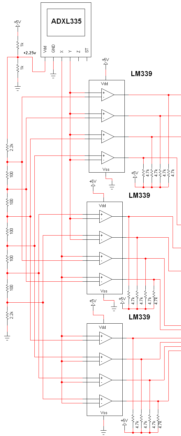
The schematic for this project is extensive, and the complete schematic is displayed below. It is divided into two sections: the analog and digital sections. The schematic illustrates the analog-to-digital conversion circuit, which includes 12 comparators—6 for the X-axis...
This amplifier circuit is designed to enhance TV signals in the UHF range. It employs a low-noise transistor, providing an amplification of 10 to 15 dB within the frequency spectrum of 400 MHz to 850 MHz. It is crucial...
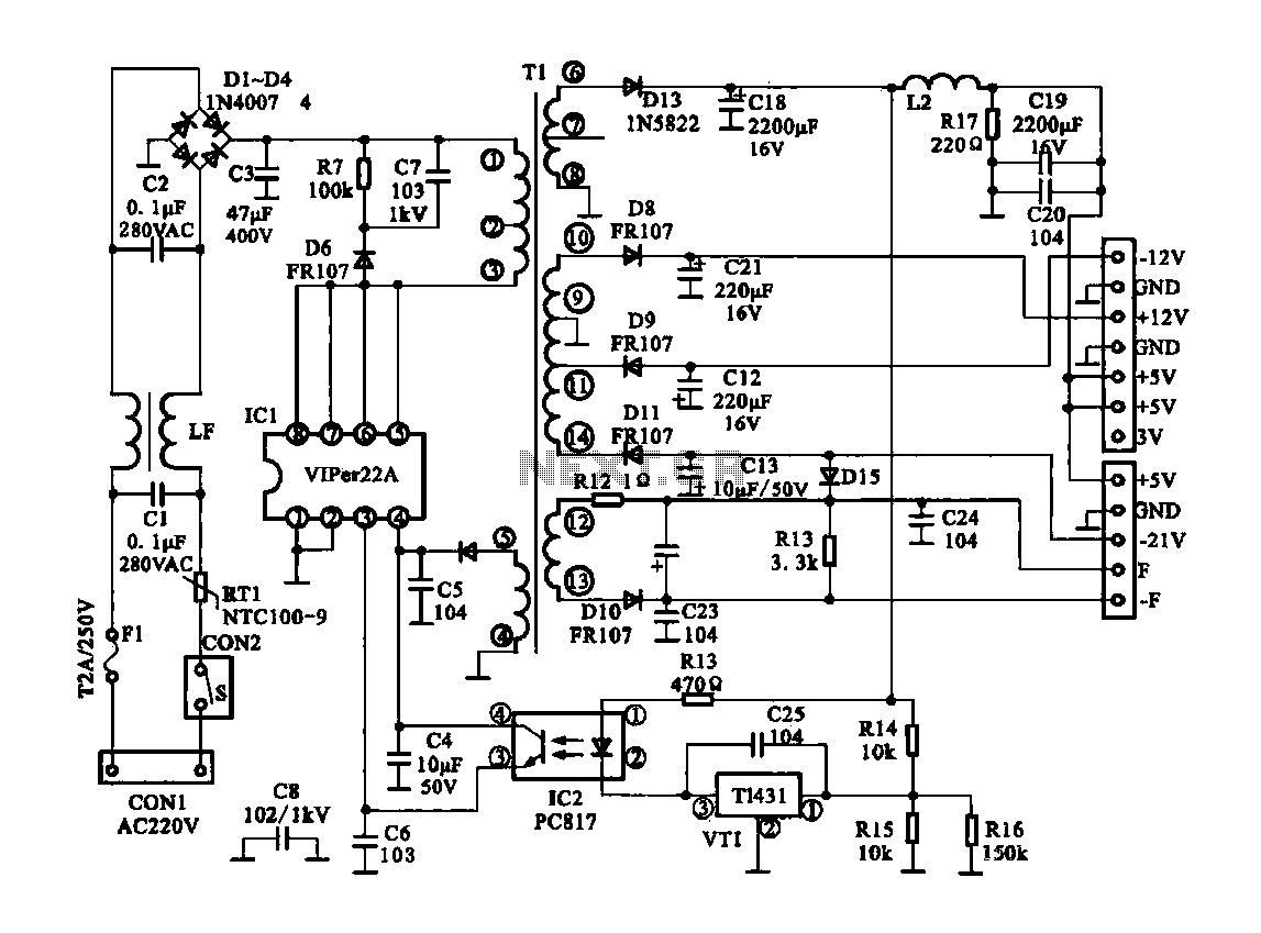
The Dragon ZL-2801A is a DVD machine that utilizes a switching power supply circuit. The circuit primarily consists of an AC input circuit, a rectifier filter wave circuit, an oscillation circuit switch, a switch transformer (Tl), a secondary rectifier,...
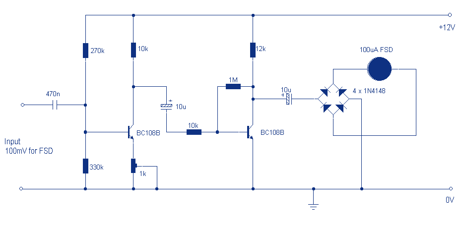
Audio levels can be monitored using a small panel meter with this circuit built from discrete components. The circuit has a flat frequency response from about 20Hz to well over 50Khz. Input sensitivity is 100mV for a full scale...
Home-built NMR spectrometer, illustrating the construction and circuitry. Demonstrates 90-degree and 180-degree pulse sequences, as well as the generation of FIDs and spin echoes at 18 MHz. The home-built NMR (Nuclear Magnetic Resonance) spectrometer is an intricate device designed for...
Figure 1-89 illustrates a loudness control circuit. A potentiometer is connected to ground, with 30% of the total resistance at the tap. When the slider arm is adjusted to the tap position, a midrange attenuation of 30 dB is...
Warning: include(partials/cookie-banner.php): Failed to open stream: Permission denied in /var/www/html/nextgr/view-circuit.php on line 713
Warning: include(): Failed opening 'partials/cookie-banner.php' for inclusion (include_path='.:/usr/share/php') in /var/www/html/nextgr/view-circuit.php on line 713