
Atari punk console + Baby sequencer 4017 IC

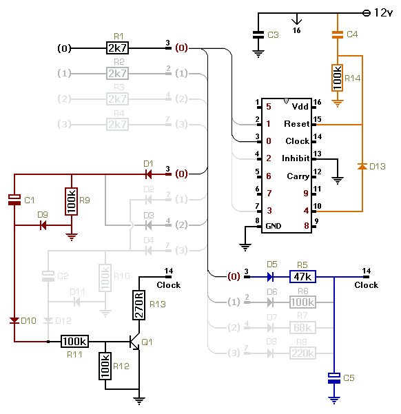
The Atari sequencer circuit primarily consists of a 555 timer configured as an astable multivibrator, which provides a clock signal to a decade counter, typically a CD4017. The clock output from the 555 timer drives the counter, which in turn sequentially activates LEDs or other output devices. The INHIBIT pin (pin 13) of the CD4017 plays a crucial role in controlling the operation of the counter. When this pin is held high, the counter is disabled, preventing it from counting. Therefore, it is critical to connect this pin to ground to ensure the counter operates as intended.
The circuit design may have variations, including the use of a DPDT switch to control the sequencing function. The user has identified that the previous switch configuration is more adaptable, allowing for simultaneous control of multiple components. The stripboard layout is being developed to reduce the footprint of the circuit while maintaining functionality. Breadboarding the design allows for testing and troubleshooting before committing to a permanent layout, which is a recommended practice for prototyping.
Issues with the circuit include a malfunctioning last LED in the sequence and a broken solder pad at the audio output, which is preventing sound from being produced. These problems necessitate careful examination of the solder connections and the overall circuit integrity. Continuous testing and adjustments will inform the user about the circuit's performance, and the user is encouraged to document any changes made during the troubleshooting process. This iterative approach will enhance understanding and skill in circuit design and assembly.Doing this atari Sequencer and I think there`s an error in the drawing can not see. the atari is working but when I press the switch to ring the Sequencer, the sound disappears. please help. I don`t know if it will solve your problem, but your pin 13 at the 4017 is the INHIBIT pin and should be tied to ground instead of being highas is in the schematic. sorry, my mistake was to directly copy the url of the image, so the image was updated and changed without my noticing, I`ll upload the old pictures that I had before the circuit was updated, only to discuss on the subject. source page is this: I opened another Argentina post on a page (this in Spanish), there user "tolemaic" raises a good system of LEDs using transistors, anyway.
the interesting thing is that in regard to replacing the switch, the DPDT, this less versatile than the last, because if you choose to sequence the first 555, the second is controlled by LDR (photoresistor), this would not be able to sequence and control the first 555 at the same time. The switches are better in the first version of the circuit. I`ve drawn up a stripboard version of this (version 3). Going to build it in the next couple of days. I`m thinking I might breadboard it first though! Just wondering if anyone here has built it yet I`ve drawn up a stripboard version of this (version 3).
Going to build it in the next couple of days. I`m thinking I might breadboard it first though! Just wondering if anyone here has built it yet Yes, I shall post the stripboard drawing. At present it is a pencil on paper job. I am just about to make up the board tonight. If it works, I shall do up an illustration in Illustrator and share. I`m probably not the best stripboarder myself. It`s about getting it into a small footprint I think, which I probably haven`t achieved just yet with this 26X18 hole version. Got the thing made up. but no go as yet. Need to go over my stripboard sketch and see if I went wrong somewhere. Will keep at it for a bit, but just wondering if anyone has had any luck with this in any fashion I`m using the oscillator switch set up from version 1 posted above, working off the diagram from version 3.
It`s 5AM here and I need some shut eye! Will get back to this tomorrow. I have a circuit i made up a few months back which is a 555 and 4017 set up. It appears to have different components in different places in relation to the 555 used for the clock. Might try hooking this up to a breadboard of the oscillator A & B part of this. First I`ll go over what I have made up tonight. On my second attempt. the sequencer is running, the last led doesn`t light for some reason. I can adjust the rate, but I`ve got a bad solder connection at the audio out so no sound. I burned off the soldering pad at that spot and have no idea how to repair that. If I work that out I`ll let you know if it works. What I`m thinking is that I am going to play around with a breadboard for a day and see if I can try get the stand alone APC and my decade counter stripboard I made some time ago, linked together.
I should probably be troubleshooting this board though. I`m still a learner as you can tell! I`m becoming increasingly aware that breadboarding designs first is a worthwhile activity! Breadboards- the staff of life! What I`m thinking is that I am going to play around with a breadboard for a day and see if I can try get the stand alone APC and my decade counter stripboard I made some time ago, linked together. I should probably be troubleshooting this board though. I`m still a learner as you can tell! I`m becoming increasingly aware that breadboarding designs first is a worthwhile activity! Breadboards- the staff of life! I`ve managed so far to get one working but never both at the same time in a convincing manner. I must have another short circuit somewhere cos all I`m getting is a whining sound and a 80 bpm sequencer pattern.
Good to see you ha 🔗 External reference
Related Circuits
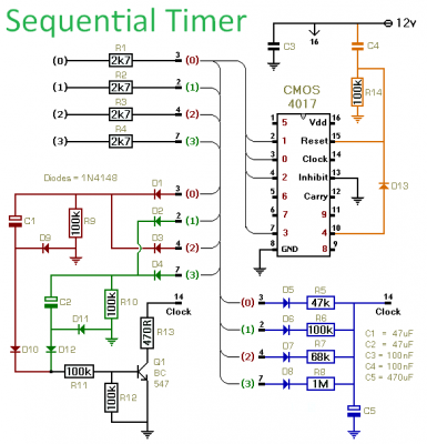
This timer is designed to generate a sequence of up to ten distinct events. Each event's duration can be set independently, and the sequence can be configured to run a predetermined number of times or continuously. Additionally, the individual...
This circuit illustrates a flip-flop timer circuit diagram utilizing the 4017 integrated circuit (IC). The key feature includes a push-button switch (S1) that discharges capacitor (C1) through resistor (R2). The 4017 decade counter IC is commonly used in timer and...
The circuit illustrated below employs a 10x10 matrix to control up to 100 LEDs using only three integrated circuits (ICs) and 20 transistors. Two 4017 decade counters manage the 10 rows and 10 columns, allowing for the selection of...
This project has been contemplated since the first attendance at a concert by Institut für Feinmotorik, a German band known for their unconventional use of turntables to produce sound and noise. What was most striking about their performance, aside...
This circuit utilizes a CMOS 4017 decade counter, which begins counting from zero and increments by one each time pin 14 is activated. Upon reaching a count of nine, it resets to zero and starts the counting process again....
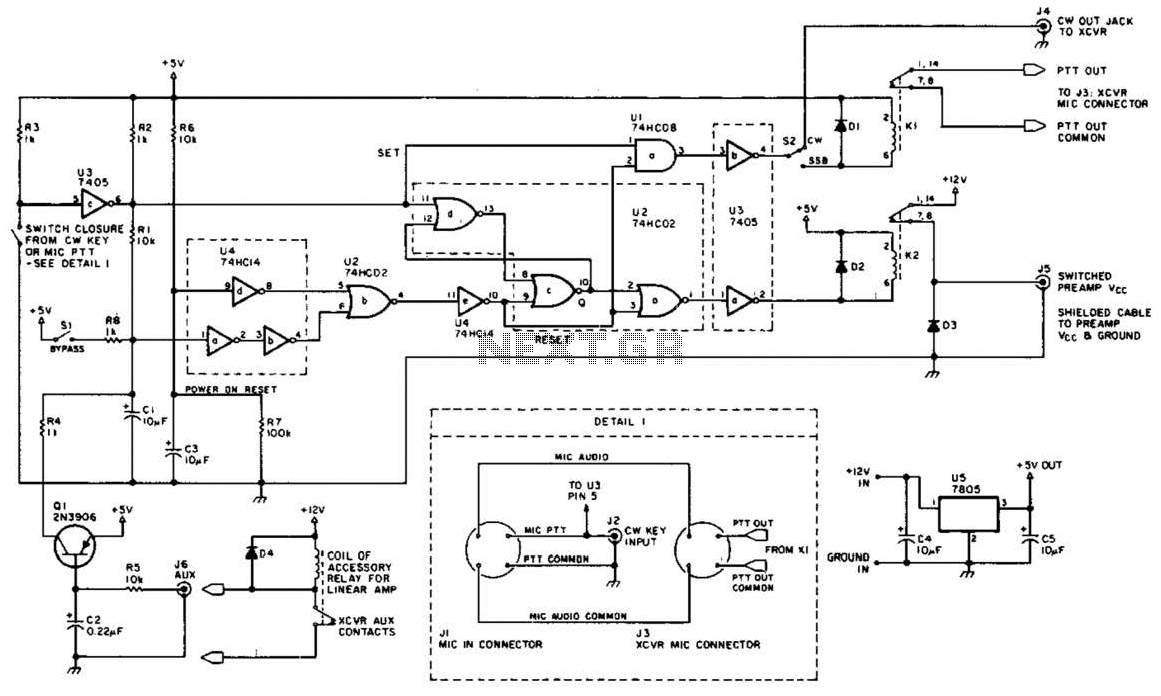
This circuit is beneficial for amateur radio operations in VHF and UHF frequencies, where a mast-mounted antenna preamplifier is employed for reception. The kit manages the transmit-receive (T-R) switching and relay sequencing to prevent high RF levels from being...