
60 Light Sequencer using a Matrix

The 10x10 LED matrix circuit is designed to efficiently manage a large number of LEDs while minimizing component count. The two 4017 decade counters serve as the core of the design, enabling the sequential activation of rows and columns. Each counter can drive 10 outputs, corresponding to the rows and columns of the matrix, ensuring that only one LED is illuminated at any given time.
In the proposed expansion to 60 LEDs, the configuration of the reset pins is crucial. By resetting the rows counter from pin 12, the circuit can cycle through additional rows, effectively increasing the range of LEDs that can be controlled. Similarly, resetting the columns counter from pin 5 allows for greater flexibility in the sequencing of the columns, accommodating the additional LEDs.
The inclusion of transistors in the circuit is essential for driving the LEDs effectively. These transistors act as switches, allowing for higher currents to flow through the LEDs than the counters can provide directly. The specified connections to the 4017 outputs ensure that each transistor is activated in sync with the counters, facilitating the desired LED illumination pattern.
For implementation, careful attention should be paid to the power supply requirements and the current ratings of the LEDs and transistors to ensure reliable operation. Additionally, the layout of the circuit should minimize interference and ensure that signal integrity is maintained, particularly in a densely packed matrix configuration. The "10 Stage LED Sequencer" reference provides detailed pin connections and configurations necessary for proper functionality, serving as a valuable resource for designers looking to replicate or modify this circuit.The circuit below illustrates using a 10x10 matrix to sequence up to 100 LEDs with just three ICs and 20 transistors. The two 4017 decade counters control the 10 rows and 10 columns so that one LED is selected depending on the output of the decade counters.
For example, to expand the circuit to 60 LEDs for displaying minutes or seconds of a clock, the rows counter could be reset from pin 12 (carry out) rather than pin 1 as shown, and the columns counter will be reset from pin 5 rather than pin 1 as shown. And then add transistors to pins 1, 5, 6, 9, and 11 of the rows counter and pin 1 of the columns counter.
Take a look at the "10 Stage LED Sequencer" for a listing of all the connections of the 4017 decade counter. 🔗 External reference
Related Circuits
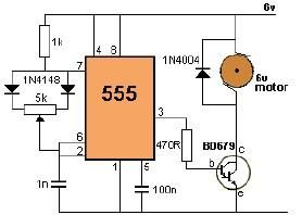
This project utilizes a 555 timer to control the speed of a 6-volt DC motor. Speed adjustment is achieved by rotating a 50 kΩ potentiometer either to the left or right. The circuit employs the 555 timer in astable mode,...
This is a capacitor power supply. This is a very small current of energy-effective because it has very little loss, much smaller than the miniature transformer. Capacitor impedance is inversely proportional to frequency. This is a great disadvantage when...
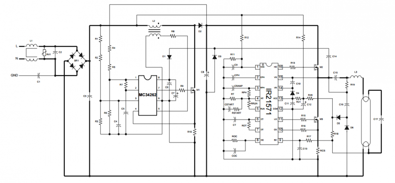
The circuit is built around the IR2520D Ballast Control IC. The IR2520D provides adjustable preheat time, adjustable run frequency to set the lamp power, high starting frequency for soft start and to avoid lamp flash, fault protection for open...
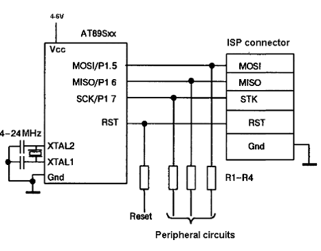
The AT89C family of microcontrollers features a parallel programming interface for flash memory. To write information, a programming voltage of 12V is required, and nearly all pins of the ports are utilized for this purpose. Consequently, parallel programming is...
The circuit below is a simple dimmer circuit. A network consisting of R1, R2, VR1, C2, C3, and Q1 controls the triggering angle of the triac by adjusting the variable resistor VR1. The described dimmer circuit employs a TRIAC (Q1)...
This is a Class D audio amplifier circuit used to control the PWM motor speed. This circuit has two advantages for battery-powered portable devices. First, it provides high efficiency, which extends battery life. The Class D audio amplifier operates by...